DMS-20RM-1-DC2-R-C Murata Power Solutions Inc, DMS-20RM-1-DC2-R-C Datasheet - Page 4
DMS-20RM-1-DC2-R-C
Manufacturer Part Number
DMS-20RM-1-DC2-R-C
Description
AC VOLTMETER 20V RANGE DC POWER
Manufacturer
Murata Power Solutions Inc
Type
Voltmeterr
Series
DMS-20RMr
Datasheet
1.DMS-20RM-2-AC1-R-C.pdf
(4 pages)
Specifications of DMS-20RM-1-DC2-R-C
Display Type
LED
Measuring Range
0 ~ 19.99VAC
Display Style
Red Characters, Black Background
Display Face Size
1.30" L x 0.80" W (33.0 x 20.3mm)
Display Digits
3.5
Display Digits - Height
0.370" (9.40mm)
Backlight
Without
Mounting Type
Panel Mount
Termination
Terminal Block
Voltage - Supply
10 ~ 40VDC
Equipment Type
AC Voltmeter
Input
20 V
Dimensions
35.1 mm L x 22.4 mm W x 51.1 mm H
Mounting Style
Panel
Primary Voltage Rating
10 V to 40 V
Secondary Current Rating
10 mA
Lead Free Status / RoHS Status
Lead free / RoHS Compliant
Lead Free Status / RoHS Status
Lead free / RoHS Compliant, Lead free / RoHS Compliant
Other names
811-1987


Panel Installation
All connections to DMS-20RM ac voltmeters must be made after the meter
is securely attached to the panel, with all associated ac supply power
sources de-energized (off). The installed wire positions should be such that
minimal forces are applied to terminal blocks TB1 and TB2. In high-vibration
environments, proper strain reliefs must be used for all wiring.
To ensure a secure panel-mount installation, MPS recommends using the
DMS-BZL4-C bezel assembly (with sealing gasket) supplied with each DMS-
20RM voltmeter. See the ‘Mechanical Specifi cations’ section for detailed
cutout and voltmeter dimensions.
Murata Power Solutions, Inc.
11 Cabot Boulevard, Mansfi eld, MA 02048-1151 U.S.A.
ISO 9001 and 14001 REGISTERED
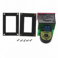
Step 1.
Step 2.
www.murata-ps.com/locations
Figure 3. Panel Installation
True-rms ac Voltmeters with Isolated Inputs
Murata Power Solutions, Inc. makes no representation that the use of its products in the circuits described herein, or the use of other
technical information contained herein, will not infringe upon existing or future patent rights. The descriptions contained herein do not imply
the granting of licenses to make, use, or sell equipment constructed in accordance therewith. Specifi cations are subject to change without
notice.
Step 3.
Following the four-step sequence shown in Figure 3 — being careful not to
apply excessive force or twisting motions — insert the DMS-20RM into the
panel opening. When using the DMS-BZL4-C, install its sealing gasket so it
is positioned between the voltmeter’s front fl ange and panel front surface
(see Mechanical Specifi cations). Be sure to use and securely tighten all four
screws supplied with the bezel assembly.
DMS-20RM Series
15 Mar 2011 MPM_DMS-20RM.A05 Page 4 of 4
Step 4.
email: sales@murata-ps.com
© 2011 Murata Power Solutions, Inc.