DMS-20RM-3-DC2-R-C Murata Power Solutions Inc, DMS-20RM-3-DC2-R-C Datasheet - Page 2
DMS-20RM-3-DC2-R-C
Manufacturer Part Number
DMS-20RM-3-DC2-R-C
Description
AC VOLTMETER 300V RANGE DC POWER
Manufacturer
Murata Power Solutions Inc
Type
Voltmeterr
Series
DMS-20RMr
Datasheet
1.DMS-20RM-2-AC1-R-C.pdf
(4 pages)
Specifications of DMS-20RM-3-DC2-R-C
Display Type
LED
Measuring Range
0 ~ 300VAC
Display Style
Red Characters, Black Background
Display Face Size
1.30" L x 0.80" W (33.0 x 20.3mm)
Display Digits
3.5
Display Digits - Height
0.370" (9.40mm)
Backlight
Without
Mounting Type
Panel Mount
Termination
Terminal Block
Voltage - Supply
10 ~ 40VDC
Equipment Type
AC Voltmeter
Input
300 V
Dimensions
35.1 mm L x 22.4 mm W x 51.1 mm H
Mounting Style
Panel
Primary Voltage Rating
10 V to 40 V
Secondary Current Rating
10 mA
Lead Free Status / RoHS Status
Lead free / RoHS Compliant
Lead Free Status / RoHS Status
Lead free / RoHS Compliant, Lead free / RoHS Compliant
Other names
811-1989


Performance/Functional Specifi cations
Typical at TA=+ 25ºC with 60Hz sine-wave input, unless otherwise noted
➀ Specifi ed accuracy applies to inputs with crest factors (CF) up to 2.0, where CF = Vpeak/Vrms.
Crest factors of 2 to 5 introduce an additional error of ±3% of full scale. Voltmeters are calibrated
with a near full-scale, 60Hz sine-wave input.
➁ Specifi ed maximum power supply currents are steady state; larger surge currents can occur at
initial application of power.
Full-Scale Input Voltage (TB2)
DMS-20RM-1
DMS-20RM-2
DMS-20RM-3
Frequency Range
Performance
Sampling Rate
Accuracy ➀
Measurement Type
Temperature Drift (0 to 60ºC)
Zero-Volt Reading (within 30 sec.)
Breakdown Voltage, TB1 to TB2
Input Impedance
Power Supply Voltage (TB1)
DMS-20RM-X-AC1
DMS-20RM-X-DC2
Power Supply Current (TB1, ➁)
DMS-20RM-X-AC1
DMS-20RM-X-DC2
Terminal Block Wiring (TB1 and TB2)
Wire Size
Insulation Strip Length
Screw Tightening Torque
Rated Voltage
Display
Display Type and Size
Overrange Indication
Decimal Point
Physical/Environmental
Operating Temperature
Storage Temperature
Humidity (non-condensing)
Dimensions
Weight:
DMS-20RM-1
DMS-20RM-2
DMS-20RM-3
2000
-001
+10.0
Fixed, model dependent (see full-scale input
Min.
-25
-40
—
—
—
47
Model dependent; see product datasheet.
0
0
0
85
—
—
0
rms responding, Crest Factors of 1-5
3½ Digit LED, 0.37”/9.4mm high
1.3 Ounces (36 grams) nominal
16-22AWG, Solid or stranded
with 60Hz sine wave input
3.6 pound-inches (0.4Nm)
2.5 reading per second
±0.2
±0.4%FS ±2 counts
Typ.
000
200
266
—
—
—
—
—
—
—
—
—
60
20
30
10
voltage above)
0.250 inches
“1___”
300Vac
+40.0
19.99
199.9
1000
Max.
±0.4
+60
+75
300
001
264
—
—
—
—
50
15
85
www.murata-ps.com/dpm
Vac/47-63Hz
mA/47-63Hz
mAdc
Counts/ºC
Counts
Units
Vac
Vac
Vac
Vdc
Vdc
kΩ
kΩ
kΩ
Hz
ºC
ºC
%
True-rms ac Voltmeters with Isolated Inputs
ORDERING INFORMATION
DMS-20RM-1-AC1-R-C
DMS-20RM-2-AC1-R-C
DMS-20RM-3-AC1-R-C
DMS-20RM-1-DC2-R-C
DMS-20RM-2-DC2-R-C
DMS-20RM-3-DC2-R-C
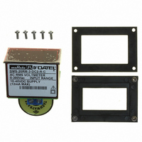
A DMS-BZL4-C bezel assembly with sealing gasket is supplied with each meter.
IMPORTANT!
voltmeters must be installed and serviced by qualifi ed technical personnel.
Contact Murata Power Solutions if there is any doubt regarding installation
and/or operation.
TECHNICAL NOTES
1. Measurement Type: DMS-20RM series ac voltmeters employ a preci-
2. Wiring: All power supply and input signal wiring must be rated for the
3. Power Supply Polarity, Fusing, and Grounding: As shown in Figures
4. Calibration: Periodic recalibration of DMS-20RM voltmeters is not
sion rms-to-dc converter and a high-precision voltage reference to
measure and display the rms value of complex ac waveforms. Please
note, the rear-mounted potential transformer is used to isolate the
input signal being measured (TB2) from the ammeter’s operating power
source connected to TB1. Do not pass any conductors through this
transformer’s center hole as this will introduce signifi cant measure-
ment errors.
voltages and currents they will carry and must comply with any code
or application-mandated requirements pertaining to the user’s specifi c
installation.
1A, 1B, and 2, the two power supply inputs, TB1-A and TB1-B, on
ac-powered DMS-20RM voltmeters (“-AC1” suffi x) are not polarity
sensitive, that is, they have no “AC LO” or “AC HI” designations. Also,
ac-powered models do not include or require a connection to earth/
chassis ground. DC-powered models (“-DC2” suffi x) are reverse-polarity
protected, and must be connected as shown in Figure 2 for proper
operation.
DMS-20RM voltmeters are not internally fused. Terminal block TB1 is to
be used only for powering the power meter’s internal circuitry; it must
not be used to supply power to external loads. The supply wires feeding
these power meters must be fused with a 0.25A/250V time delay/time
lag fuse, in accordance with applicable regulatory codes.
Wire insulation must be stripped to within ±10% of the stated dimen-
sions, and wires should be inserted into TB1 such that their insulation
is not pinched by the screw terminal. See the Functional Specifi cations
section of this data sheet for wire sizes and tightening torque for TB1’s
screw terminals.
required under normal, indoor operating environments. If calibration is
necessary, it should only be performed by qualifi ed technical personnel.
Calibration is performed with potentially lethal voltages applied to the
DMS-20RM and its associated wiring. A plastic, fully-insulated adjust-
ing tool must be used to access the recessed calibration potentiometer
located on the back of the unit (see Mechanical Specifi cations). Contact
Murata Power Solutions if additional information is required regarding
calibration, setup, or any other technical issue pertaining to DMS-20RM
ac voltmeters.
To ensure safe and reliable operation, DMS-20RM ac
DMS-20RM Series
15 Mar 2011 MPM_DMS-20RM.A05 Page 2 of 4
0 to 19.99Vac, AC Powered
0 to 199.9Vac, AC Powered
0 to 300Vac, AC Powered
0 to 19.99Vac, DC Powered
0 to 199.9Vac, DC Powered
0 to 300Vac, DC Powered
email: sales@murata-ps.com