DMU-30DCV-2-DR-C Murata Power Solutions Inc, DMU-30DCV-2-DR-C Datasheet - Page 2
DMU-30DCV-2-DR-C
Manufacturer Part Number
DMU-30DCV-2-DR-C
Description
VOLT METER LED 20DCV 0.01V RED
Manufacturer
Murata Power Solutions Inc
Type
Voltmeterr
Series
DMU-30DCVr
Datasheet
1.DMU-30DCV-2-DR-C.pdf
(3 pages)
Specifications of DMU-30DCV-2-DR-C
Display Type
LED
Measuring Range
0 ~ 19.99VDC
Display Style
Red Characters, Black Background
Display Digits
3.5
Display Digits - Height
0.560" (14.22mm)
Backlight
Without
Mounting Type
Panel Mount
Termination
Terminal Block
Voltage - Supply
85 ~ 264VAC
Equipment Type
DC Voltmeter
Input
19.99 V
Dimensions
72.39 mm L x 40.64 mm W x 44.7 mm H
Mounting Style
Panel
Primary Voltage Rating
85 V to 264 V
Secondary Voltage Rating
110 VDC to 300 VDC
Lead Free Status / RoHS Status
Lead free / RoHS Compliant
Display Face Size
-
Lead Free Status / Rohs Status
Lead free / RoHS Compliant
Other names
811-1943
Available stocks
Company
Part Number
Manufacturer
Quantity
Price
Company:

Part Number:
DMU-30DCV-2-DR-C
Manufacturer:
Murata Power Solutions Inc
Quantity:
135


TECHNICAL NOTES (continued)
4. Calibration: Periodic recalibration of DMU-30DCV voltmeters is not required
5. Minimum-Intensity Adjustment Potentiometer: Users can adjust the
6. Operation with Power Supplies Lower than 85Vac: In indoor applications
7. Panel Installation: All electrical connections to DMU-30DCV must be made
Ordering Information
Model
DMU-30DCV-0-DR-C
DMU-30DCV-1-DR-C
DMU-30DCV-2-DR-C
DMU-30DCV-3-DR-C
under normal indoor operating environments. However, operation in environ-
ments subject to vibration and/or extreme temperature variations should
have their accuracy verifi ed on a yearly basis. If recalibration is necessary,
it should only be performed by qualifi ed technical personnel. Calibration is
performed with potentially lethal voltages applied to the DMU-30DCV and
its associated wiring. A plastic, fully-insulated adjusting tool must be used
to access the recessed calibration potentiometer located on the back of the
unit (see Mechanical Specifi cations). Contact Murata / DATEL if additional
information is required regarding calibration, setup, or any other technical
issue pertaining to DMU-30DCV dc voltmeters.
DMU-30DCV’s minimum LED display brightness to suit their indoor viewing
requirements by adjusting the ¾-turn, rear-mounted intensity adjustment
potentiometer. Please note, this potentiometer will have minimal impact on
display brightness in high ambient light environments.
The intensity adjustment potentiometer is factory preset to its mid-point po-
sition. As viewed from the rear of the meter, and with the model number label
facing up, turning the potentiometer clockwise increases the LED display’s
intensity. See the Mechanical Specifi cations section for potentiometer loca-
tions.
where daylight readability (i.e., maximum display brightness) is not required,
DMU-30DCV meters will meet their specifi ed accuracy with ac supply volt-
ages (TB1) well below 85Vac. While performance is not guaranteed, DMU-
30DCV voltmeters remain easily readable and accurate with ac supplies as
low as 20Vac.
after the meter is securely attached to the panel and with all input and
supply voltages de-energized (off). Care must be exercised when attach-
ing conductors to terminal blocks TB1 and TB2. The installed wire-positions
should be such that minimal forces are applied to the terminal blocks or the
voltmeter. In high-vibration environments, adequate strain reliefs must be
used on all input and supply wiring.
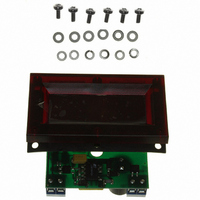
To ensure a secure and moisture/vibration resistant installation, use only
the supplied hardware. Following the four-step sequence shown—being
careful not to apply excessive force or twisting motions—insert the voltmeter
into the panel opening. Tighten all six M3 metric screws to 3 inch-pounds
(0.34Nm). See the Mechanical Specifi cations section for panel cutout, drill
dimensions, and panel installation information.
Input Range
0 to ±199.9mVdc
0 to ±1.999Vdc
0 to ±19.99Vdc
0 to ±199.9Vdc
www.murata-ps.com/dpm
Performance/Functional Specifi cations
Typical at T
➀ Display reading is set to “1888”. Specifi ed power supply currents are steady state; larger
Ruggedized DC Voltmeters with Daylight Readable
Input (TB2)
Full Scale Input Range:
DMU-30DCV-0-DR-C
DMU-30DCV-1-DR-C
DMU-30DCV-2-DR-C
DMU-30DCV-3-DR-C
Performance
Sampling Rate
Accuracy
Zero Reading (within 30 sec.)
Temperature Drift (0 to +60°C)
Breakdown Voltage (TB1 to TB2)
Supply Voltage (TB1)
DMU-30DCV
Supply Current (TB1)
DMU-30DCV (total darkness)
DMU-30DCV (full sunlight)
Terminal Block Wiring (TB1 & TB2)
Wire Size
Insulation Strip Length
Screw Tightening Torque
Rated Voltage
Display
Display Type and Size
Decimal Point
Overrange Indication
Physical/Environmental
Operating Temperature
Storage Temperature
Humidity (non-condensing)
Dimensions
Weight
surge currents can occur at initial application of ac power. Power supply input (TB1) set to
120Vac/60 Hz.
A
= +25°C, unless otherwise noted.
c
DMU-30DCV Series
24 Mar 2011 MPM_DMU_30DCV.A07 Page 2 of 3
Auto-Dimming LED Displays
“–001”
3½ digit, 0.56"/14.2mm high red LED
Min.
2000
–25
–40
Daylight readable, auto-dimming,
0
0
0
0
–
0
85
–
–
1.3 ounces (36 grams) nominal
See mechanical specifi cations
16-22 AWG, Solid or stranded
email: sales@murata-ps.com
3.6 pound-inches (0.4Nm)
2.5 readings per second
Fixed, model dependent
±0.4%FS ±2 counts
0.250 inches (6.35)
“000”
Typ.
±0.2
–
–
–
–
–
–
–
–
40
–
4
"1_ _ _ "
300Vac
Max.
199.9
1.999
19.99
199.9
“001”
±0.4
+60
+75
264
85
50
–
6
Vac/47-
63Hz
mA/47-
63Hz
mA/47-
63Hz
Cnts/°C
Units
mVdc
Cnts
Vdc
Vdc
Vdc
Vdc
°C
°C
%