ACA-20RM-5-AC4-RL-ALM-C Murata Power Solutions Inc, ACA-20RM-5-AC4-RL-ALM-C Datasheet - Page 3
ACA-20RM-5-AC4-RL-ALM-C
Manufacturer Part Number
ACA-20RM-5-AC4-RL-ALM-C
Description
AMMETER AC 30A 220V W/ALARM RED
Manufacturer
Murata Power Solutions Inc
Series
ACA-20RM-ALMr
Type
Ammeterr
Datasheet
1.ACA-20RM-5-AC3-RL-ALM-C.pdf
(5 pages)
Specifications of ACA-20RM-5-AC4-RL-ALM-C
Display Type
LED
Measuring Range
0 ~ 30.0A
Display Style
Red Characters, Black Background
Display Digits
3.5
Display Digits - Height
0.370" (9.40mm)
Backlight
Without
Mounting Type
Panel Mount
Termination
Terminal Block
Voltage - Supply
170 ~ 264VAC
Dimensions
53.34 mm L x 35.56 mm W x 18.54 mm H
Mounting Style
Panel
Primary Voltage Rating
170 V to 264 V
Secondary Current Rating
30 A
Lead Free Status / RoHS Status
Lead free / RoHS Compliant
Display Face Size
-
Lead Free Status / Rohs Status
Lead free / RoHS Compliant
Other names
811-1983


To adjust the overcurrent alarm set-point level:
4. Wire Gauges and Fusing: Wires specifi ed in the Functional Specifi ca-
5. AC Supply Polarity and Grounding: The two supply inputs, TB1-A and
6. Connector Torque Ratings: It is important to tighten TB1’s, screw-ter-
Please note, the load circuit does not need to be turned off to adjust the
overcurrent alarm set point. Current fl owing through L1 while JP1 is
across terminals 1 and 2 will not be measured. Once tripped, the alarm
set point function has a hysteresis of approximately 0.5A.
The overcurrent alarm function can also be adjusted with JP1 in its
normal operation position if the desired alarm overcurrent-level is
actually fl owing through L1 (i.e., with a live load). For example, with
a 20 Amp load current fl owing through L1, and with JP1 in its normal
operation position, slowly adjust R3 until the display starts fl ashing on
and off. Using this “live load” adjustment method eliminates the need
to turn off power to TB1 or reconfi guring JP1.
tions section must be used for making connections to ACA-20RM-ALM
series ammeters. All power-supply and load wiring must be rated for
the supply voltages and currents they will conduct and must comply
with any code or application-mandated requirements pertaining to the
user’s specifi c installation.
ACA-20RM-ALM ammeters are not internally fused. Terminal block TB1
is to be used only for powering the ammeter’s internal circuitry; it must
not be used to supply power to external loads. The supply wires feed-
ing these power meters must be fused with a 0.25A/250V time delay/
time lag fuse, in accordance with applicable regulatory codes.
Wire insulation must be stripped to within ±10% of the stated dimen-
sions, and wires should be inserted into TB1 such that their insulation
is not pinched by the screw terminal.
TB1-B, on ACA-20RM-ALM ammeters are not in themselves polarity
sensitive, that is, they have no internal “AC LO” or “AC HI” designa-
tions. ACA-20RM-ALM ammeters do not include or require a connec-
tion to earth/chassis ground.
minals to their rated torque specifi cation of 3.6 pound-inches (0.4Nm).
Proper tightening will minimize connector losses and ensure safe,
reliable operation.
A. Turn off power to the ACA-20RM-ALM (i.e., the power source con-
B. Carefully remove the shorting jumper across JP1 from its ‘normal
C. Re-apply power to TB1 and, using a plastic insulated adjusting tool,
D. Turn off power to the ACA-20RM-ALM and return JP1’a shorting
nected to TB1).
operation position’ across terminals 2 and 3 and place it across JP1
terminals 1 and 2.
adjust R3 so the ammeter’s display shows the desired overcurrent
trip level in Amps.
jumper back to its ‘normal operation position’ across terminals 2
and 3. Re-apply power to TB1 to resume normal operation. If pos-
sible, after the ammeter is re-confi gured for normal operation, the
load current should be slowly increased to verify the visual alarm
operates when the load current exceeds the preset level.
www.murata-ps.com/dpm
7. Isolation: The built-in current transformer L1 provides a minimum
8. Split-Core CT (Clamp-on) Models: Both 50A models feature a split-
TB1
of 2000Vdc isolation between the load conductor and the ammeter’s
supply voltage connected to TB1.
core current transformer that can be clamped around a properly insu-
lated live conductor without having to disconnect or remove power
from the load circuit. This live-connection capability can only be used
if the load’s power source is electrically isolated (see technical note
7) from the ammeter’s own power source that’s connected to TB1.
The ammeter’s ac power supply must always be denergized before
making connections to TB1. Refer to the ‘Panel Installation’ section of
this data sheet for additional information.
BACK VIEW
FUSED AC POWER
TO AC LOAD
True-rms-AC Ammeters with Alarm Function
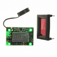
Figure 3. Alarm circuit component location
ACA-20RM-ALM Series
15 Mar 2011 MPM_ACA-20RM-ALM.A04 Page 3 of 5
JP1
3
2
1
A
B
Figure 2. Typical wiring diagram
TB1
ALARM
CAL
R7
R3
BACK VIEW
email: sales@murata-ps.com
L1
3
2
1
3
2
1
JP1
Normal Operation
JP1
Overcurrent
Alarm Adjustment