V600 Martel Electronics, V600 Datasheet - Page 3
V600
Manufacturer Part Number
V600
Description
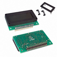
VOLTMETER LCD 200MV 0.6" DIG HT
Manufacturer
Martel Electronics
Series
Vr
Type
Voltmeterr
Datasheet
1.V600.pdf
(4 pages)
Specifications of V600
Measuring Range
200mVDC
Display Style
Black Characters, Grey Background
Display Type
LCD
Display Face Size
1.86" L x 0.98" W (47.0 x 25.0mm)
Display Digits
3.5
Display Digits - Height
0.591" (15.00mm)
Backlight
Without
Mounting Type
Panel Mount
Termination
PC Pins
Voltage - Supply
7 ~ 12VDC
Lead Free Status / RoHS Status
Lead free / RoHS Compliant
Other names
227-1061
Available stocks
Company
Part Number
Manufacturer
Quantity
Price
Company:

Part Number:
V600-H11 0.5M
Manufacturer:
OMRON
Quantity:
1 000
Company:
Part Number:
V600-H11 10M
Manufacturer:
OMRON
Quantity:
1 000
Company:
Part Number:
V600-H11 2M
Manufacturer:
OMRON
Quantity:
1 000
Company:
Part Number:
V600-H11 5M
Manufacturer:
OMRON
Quantity:
1 000
Company:
Part Number:
V600-HA51 0.5M
Manufacturer:
OMRON
Quantity:
1 000
Part Number:
V600ME02-LF
Manufacturer:
Z-COMM
Quantity:
20 000


PIN FUNCTIONS
1.
2.
3.
4.
5.
6.
7.
8.
9.
10. RFL
11. VSS
12. INLO
13. INHI
14. TEST
15. VDD
Solder Links:
BP
BAT
CIRCUIT DIAGRAM
INLO
COM
ROH
VDD
INHI
ROL
RFH
RFL
VSS
BP
LO BAT LCD connection to "Low Battery" annunciator.
DP1
DP2
DP3
ROH
ROL
COM
RFH
15
13
12
10
7
11
8
9
6
VDD
This pin is nominally at 5V below VDD and is the ground for the digital section of the meter, it can be used as a negative
supply to power external logic up to a maximum of 1mA.
Positive power supply connection.
Normally Open.
Normally Open.
Backplane connection from voltmeter IC.
Connect to V+ to display Decimal Point 1 (1.999).
Connect to VDD to display Decimal Point 2 (19.99).
Connect to VDD to display Decimal Point 3 (199.9).
Positive output from internal reference.
Negative output from internal reference.
The ground for the analogue section of the A/D converter, held actively at 2.8V (nom) below VDD.
COM must not be allowed to sink excessive current (> 100 A) by connecting it directly to a higher voltage.
Positive input for reference voltage.
Negative input for reference voltage.
Negative power supply connection.
Negative measuring input with reference to IN HI.
Positive measuring input with reference to IN LO.
Connecting this pin to VDD to turn on display segments "-1888".
It should not be operated for more than a few seconds as the DC voltage applied to the LCD may "burn" the display.
1M
R2
R6
100k
R5
3k
R4
1.5k
100nF
300k
C3
R1
100nF
R3
220nF
68nF
C4
C1
C2
100k
C5
100pF
27
28
29
31
30
32
34
33
36
35
40
39
38
INT
BUF
A/Z
IN HI
IN LO
COM
CREF+
CREF-
REF HI
REF LO
OSC1
OSC2
OSC3
IC1
V+
V- TEST
26
1
POL
bc4
37
www.martelmeters.com
BP
a1
b1
d1
e1
a2
b2
d2
e2
a3
b3
d3
e3
c1
g1
c2
g2
c3
g3
f1
f2
f3
5
4
3
2
8
6
7
12
11
10
9
14
13
25
23
16
24
15
18
17
22
19
20
21
17
16
15
14
13
18
19
21
11
10
22
23
25
24
26
27
28
30
20
See application diagram on next page.
Analogue inputs must be no closer than 1V
to either the positive or negative supply.
9
7
6
5
3
2
1
a1
b1
c1
d1
e1
f1
g1
a2
b2
c2
d2
e2
f2
g2
a3
b3
c3
d3
e3
f3
g3
b4
c4
POL
COM
COM
LCD1
LOBAT
DP1
DP2
DP3
29
1.999
4
19.99
8
199.9
12
3½ Digit LCD Voltmeter Module
IC2
4070
VDD
10
11
4
3
IC2D
IC2A
IC2C
IC2B
14
7
5
6
2
1
12
13
9
8
R9
1M
BAT
BP
R8
1M
page 3 of 4
R7
1M
14
2
3
4
5
1
LO BAT
BP
DP1
DP2
DP3
TEST