DMS-30DR-2-R-C Murata Power Solutions Inc, DMS-30DR-2-R-C Datasheet - Page 4
DMS-30DR-2-R-C
Manufacturer Part Number
DMS-30DR-2-R-C
Description
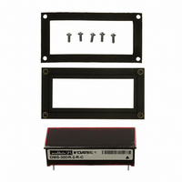
DPM LED 20V 3.5DIG DAYLIGHT RED
Manufacturer
Murata Power Solutions Inc
Type
Voltmeterr
Series
DMS-30DRr
Datasheet
1.DMS-30DR-1-R-C.pdf
(6 pages)
Specifications of DMS-30DR-2-R-C
Display Type
LED
Measuring Range
±20V
Display Style
Red Characters, Black Background
Display Face Size
2.09" L x 0.84" W (53.1 x 21.3mm)
Display Digits
3.5
Display Digits - Height
0.560" (14.22mm)
Backlight
Without
Mounting Type
Panel Mount
Termination
PC Pins
Voltage - Supply
4.75 ~ 5.25V
Equipment Type
Panel Meters
Lead Free Status / RoHS Status
Lead free / RoHS Compliant
Lead Free Status / RoHS Status
Lead free / RoHS Compliant, Lead free / RoHS Compliant
Other names
811-1035
Available stocks
Company
Part Number
Manufacturer
Quantity
Price

Part Number:
DMS-30DR-2-R-C
Manufacturer:
MURATA/村田
Quantity:
20 000


3. Engineering Scaling: For measuring voltages greater than the full
2. Differential Input Confi gurations: Differential measurements can be
APPLICATIONS
scale input range of a given meter, the input signal must be attenuated.
A simple voltage divider (similar to that shown in Figure 4) will scale
the input to within the range of the selected meter. R1 and R2 should
be precision, ±1%, metal-fi lm resistors with absolute TCR's less than
50ppm/°C. See Ap Note 4 for more information on engineering scaling.
made with all DMS-30DR meters. Figure 3, though not a practical real-
world application, uses a voltage divider to demonstrate the concept
of a differential input signal. Be careful not to exceed the ±2V common
mode voltage limitation for 5V-powered meters.
85-264Vac
+
–
85-264Vac
V
REF OUT
IN
REF IN
DP1
R1
R2
AC to DC Converter
8
7
6
Figure 3. Differential Input Confi guration
(–) IN LO
(+) IN HI
50kΩ < R1 + R2 < 10MΩ
R1 + R2
Figure 4. Input Attenuation Circuit
R2
11
12
+5V SUP
+5V SUP
x V
DMS-30DR-1
IN
1
1
= Reading
DMS-30DR-1
3
5V RET
5V RET
3
11
(+) IN HI
12
(–) IN LO
www.murata-ps.com/dpm
7
8
REF OUT
REF IN
R1
R2
R3
1k
1k
1k
85-264Vac
CELL
1.5V
CELL
85-264Vac
1.5V
5. Process Control (4-to-20mA) Measurements: In many common pro-
4. Floating Signal Source Measurements: Floating signals can be
Where:
cess-control applications, a 4-to-20mA current loop is used to transmit
information. Because DMS-30DR meters have such high input imped-
ance, a simple shunt resistor across the meter's input can be used to
convert the loop current to a voltage. See Figure 7. The value of the
shunt resistor is a function of the scaling requirements of the particular
application and can be calculated using the following equation:
measured using the circuits shown in Figures 5 and 6. Connecting pin
10 (ANALOG COMMON) or pin 3 (5V RETURN) to (–) INPUT LO (pin
12) provides the reference point for the meter's input.
A "fl oating" input is a signal that has no galvanic connection to the
meter's power supply. In the fi gures below, the 1.5V battery illustrates a
true fl oating input.
AC to DC Converter
–
–
AC to DC Converter
R
Shunt
V
ANA COMM
I
Fsr
Fsr
(–) IN LO
(+) IN HI
(–) IN LO
(+) IN HI
Figure 6. Floating Input Measurements
Figure 5. Floating Input Measurements
= R1 = V
= Full scale reading (in Volts)
= Relative full scale current (in Amps)
11
12
11
10
12
+5V SUP
Sunlight Readable, 3½ Digit Panel Meters
(Alternate Confi guration)
+5V SUP
1
Fsr
DMS-30DR Series
03 Aug 2010 MPM_DMS-30DR.B05 Page 4 of 6
1
/ I
Fsr
with Auto-Dimming LED Displays
5V RET
DMS-30DR-1
5V RET
DMS-30DR-1
3
3
email: sales@murata-ps.com
DP1
6
DP1
6
8
REF OUT
7
REF IN
8
7
REF OUT
REF IN