DMS-30PC-4/20S-24BS-I-C Murata Power Solutions Inc, DMS-30PC-4/20S-24BS-I-C Datasheet - Page 3
DMS-30PC-4/20S-24BS-I-C
Manufacturer Part Number
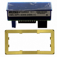
DMS-30PC-4/20S-24BS-I-C
Description
DPM LED 24V SUPPLY 3.5DIG BLUE
Manufacturer
Murata Power Solutions Inc
Series
DMS-30PC-4/20Sr
Type
Process Meter (4-20mA Loop)r
Datasheet
1.DMS-30PC-420S-24RS-I-C.pdf
(4 pages)
Specifications of DMS-30PC-4/20S-24BS-I-C
Display Type
LED
Measuring Range
4-20mA Loop
Display Style
Blue Characters, Black Background
Display Face Size
2.09" L x 0.84" W (53.1 x 21.3mm)
Display Digits
3.5
Display Digits - Height
0.560" (14.22mm)
Backlight
Without
Mounting Type
Panel Mount
Termination
Terminal Block
Voltage - Supply
21.6 ~ 26.4VDC
Dimensions
55 mm L x 23 mm W x 27 mm H
Mounting Style
Panel
Primary Voltage Rating
5 V
Lead Free Status / RoHS Status
Lead free / RoHS Compliant
Lead Free Status / RoHS Status
Lead free / RoHS Compliant, Lead free / RoHS Compliant
Other names
811-1081
Available stocks
Company
Part Number
Manufacturer
Quantity
Price
Company:

Part Number:
DMS-30PC-4/20S-24BS-I-C
Manufacturer:
Murata Power Solutions Inc
Quantity:
135


1. Desired display readings are:
2. Desired display readings are:
CONNECTION DIAGRAMS
3. Desired display readings are:
Examples
+24V
Use DIP-switch setting #1 and enable decimal point DP2 via SW6.
Apply 4mA and adjust R3 so the display reads "0.00". Apply 20mA and
adjust R7 so the display reads "2.00".
Use DIP-switch setting #4. Apply 12mA and adjust R3 so the display
reads "000". Apply 20mA and adjust R7 so the display reads "100".
Apply 4mA and the display should read "–100". For these display read-
ings, no decimal points are used. Set SW5, SW6 and SW7 to OFF.
4mA ="0.00"
4mA = "–100"
This example is not as straightforward as the previous two. Notice that
12mA is exactly halfway between 4mA and 20mA. If we assume the
input could go up to 20mA, the display reading would be: 2 x .250 or
".500". From the table, we can select DIP-switch setting #2 and enable
DP1 via SW5. Apply 4mA and adjust R3 so the display reads ".000".
Apply 12mA and adjust R7 so the display reads ".250".
SINGLE-ENDED
TRANSMITTER
Figure 2. Typical Connections for Single-Ended Transmitters Driving
+
20mA = "2.00"
12mA = "000"
20mA = "100"
4mA = ".000"
12mA = ".250"
24V GROUND
+
–
Single-Ended +24V Powered Meters.
4-20mA
(TB1-1)
(TB1-2)
+
–
1
1
1
1
1
1
2
2
1
1
1
2
2
3
3
2
2
DMS-30PC-4/20S-24RL
3
3
4
4
3
3
ON
ON
+V
–V (TB2-2)
4
4
4
4
5
5
ON
ON
(TB2-1)
ON
ON
5
5
6
6
5
5
www.murata-ps.com/dpm
6
6
6
6
7
7
7
7
8
8
7
7
8
8
8
8
+24V
Figure 5. Typical Connections for +5V Powered Meters. Note that 5V Ground
+24V
LOOP-POWERED
TRANSMITTER
TRANSMITTER
SINGLE-ENDED
TRANSMITTER
LOOP
+24V
Figure 3. Typical Connections for Loop-Powered Transmitters
Figure 6. Typical Connections for Loop-Powered Transmitters
+
+
24V GROUND
+
24V GROUND
Driving Isolated-Supply Meters (-I part number suffi x).
and 24V Ground are Tied Together Inside the Meter.
Figure 4. Typical Connections for Isolated-Supply Meters
+
–
–
–
+
4-20mA Input 3½ Digit Panel Meters
4-20mA
4-20mA
Driving Single-Ended Meters.
+
in Series with an Auxiliary Device
24 Mar 2011 MPM_DMS-30PC-420S.B04 Page 3 of 4
N.C.
(TB1-1)
4-20mA
DMS-30PC-4/20S-24RL-I
(TB1-1)
(TB1-2)
(TB1-1)
(TB1-2)
DMS-30PC-4/20S
with Full-Size LED Displays
+V (TB2-1)
+
–
+
–
4-20mA
(TB1-2)
email: sales@murata-ps.com
DMS-30PC-4/20S-24RL
DMS-30PC-4/20S-24RL
DMS-30PC-4/20S-24XX-I
–
+V
+V
–V (TB2-2)
–V (TB2-2)
+5V
–V
(TB2-2)
(TB2-1)
(TB2-1)
24V GROUND
5V GROUND
+
–
SINGLE-ENDED
PLC or OTHER
DEVICE