DMS-40PC-4/20S-24RS-I-C Murata Power Solutions Inc, DMS-40PC-4/20S-24RS-I-C Datasheet - Page 4
DMS-40PC-4/20S-24RS-I-C
Manufacturer Part Number
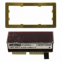
DMS-40PC-4/20S-24RS-I-C
Description
METER DISP LED 4.5DIG 24V RED
Manufacturer
Murata Power Solutions Inc
Series
DMS-40PC-4/20Sr
Type
Process Meter (4-20mA Loop)r
Datasheet
1.DMS-40PC-420S-24RS-I-C.pdf
(6 pages)
Specifications of DMS-40PC-4/20S-24RS-I-C
Display Type
LED
Measuring Range
4-20mA Loop
Display Style
Red Characters, Black Background
Display Face Size
2.09" L x 0.84" W (53.1 x 21.3mm)
Display Digits
4.5
Display Digits - Height
0.520" (13.21mm)
Backlight
Without
Mounting Type
Panel Mount
Termination
Terminal Block
Voltage - Supply
21.6 ~ 26.4VDC
Input
4 mA to 20 mA
Mounting Style
Panel
Number Of Outputs
1
Lead Free Status / RoHS Status
Lead free / RoHS Compliant
Lead Free Status / RoHS Status
Lead free / RoHS Compliant, Lead free / RoHS Compliant
Other names
811-1082
Available stocks
Company
Part Number
Manufacturer
Quantity
Price
Company:

Part Number:
DMS-40PC-4/20S-24RS-I-C
Manufacturer:
Murata Power Solutions Inc
Quantity:
135


4. If necessary, select the appropriate decimal point by setting either
NOTE: Please keep in mind that the transmitter's 4mA and 20mA output
accuracy may affect display readings which are at, or very close to, the
high and low extremes of the selected range. See Example #2 below and
Technical Note 1 for more information.
Examples
The examples below illustrate how to configure the meter to perform
some typical measurements. Remember to first set R3 and R7 to their full
clockwise position before calibrating the meter.
1. Desired display readings are:
Use DIP-switch setting #3 and enable decimal point DP2 by placing SW4
of switch S2 to ON. Apply 4mA and adjust R3 so the display reads "0.000".
Apply 20mA and adjust R7 so the display reads "3.000".
2. Desired display readings are:
CONNECTION DIAGRAMS
SW3, SW4, SW5, or SW6 of S2 to ON (DP1, DP2, DP3, or DP4,
respectively, as shown in Table 2).
4mA = "0.000"
20mA = "3.000"
4mA = "0000"
20mA = "8600"
+24V
SINGLE-ENDED
TRANSMITTER
1
1
1
1
1
1
2
2
2
2
+
3
3
3
3
24V GROUND
ON
ON
ON
S1
S1
4
4
4
4
ON
Figure 2. Typical Connections for Single-Ended Transmitters Driving
www.murata-ps.com
5
5
5
5
+
–
6
6
6
6
4-20mA
S2
S2
Single-Ended +24V Powered Meters.
1
1
1
1
1
1
2
2
2
2
(TB1-1)
(TB1-2)
+
–
Use DIP-switch setting #11. Apply 4mA and adjust R3 so the display
reads "0000". Apply 20mA and adjust R7 so the display reads "8600". If
the transmitter's full-scale output is less than 20.0mA, it may not be pos-
sible to adjust R7 for a reading of "8600" with setting #11. If this occurs,
select setting #12 and re-calibrate both R3 and R7 to obtain "0000" and
"8600". Note that for these display readings no decimal points are used.
Set SW3, SW4, SW5 and SW6 on switch S2 to OFF.
3. Desired display readings are:
Use DIP-switch setting #13. Apply 4mA and adjust R3 so the display
reads "0000". Apply 20mA and adjust R7 so the display reads "10000".
For these display readings no decimal points are used. Set SW3, SW4,
SW5 and SW6 on switch S2 to OFF.
4. Desired display readings are:
This example is not as straightforward as the previous three. Notice that
12mA is exactly halfway between 4mA and 20mA. If we assume the input
could go up to 20mA, the display reading would then be 2 x .2500 or
".5000". From the table, we can select DIP-switch setting #7 and enable
DP1 via SW3 of switch S2. Apply 4mA and adjust R3 so the display reads
".0000". Apply 12mA and adjust R7 so the display reads ".2500".
4½ Digit, 4-20mA Input, LED Display Meters
DMS-40PC-4/20S-24RL
4mA = "0000"
20mA = "10000"
4mA = ".0000"
12mA = ".2500"
+V
–V (TB2-2)
Technical enquiries email: sales@murata-ps.com, tel:
(TB2-1)
DMS-40PC-4/20S
1
1
1
1
1
1
MPM_DMS-40PC-420.D02 Page 4 of 6
2
2
2
2
3
3
3
3
S1
ON
ON
S1
4
4
4
4
ON
ON
5
5
5
5
6
6
6
6
+1 508 339 3000
S2
S2
1
1
1
1
1
1
2
2
2
2