DPM2000-20 Martel Electronics, DPM2000-20 Datasheet - Page 2
DPM2000-20
Manufacturer Part Number
DPM2000-20
Description
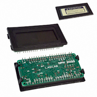
METER DPM LCD 3.5DIGIT 20V IN
Manufacturer
Martel Electronics
Series
Legacyr
Type
Voltmeterr
Datasheet
1.DPM2000-2.pdf
(2 pages)
Specifications of DPM2000-20
Measuring Range
20V
Display Style
Black Characters, Grey Background
Display Type
LCD
Display Face Size
2.38" L x 1.42" W (72.0 x 36.0mm)
Display Digits
3.5
Display Digits - Height
0.591" (15.00mm)
Backlight
Without
Mounting Type
Panel Mount
Termination
Solder Pads
Voltage - Supply
7.5 ~ 14V
Lead Free Status / RoHS Status
Lead free / RoHS Compliant
Other names
227-1029


Specifications liable to change without prior warning
PIN FUNCTIONS
8, 10, 15, 19
SPECIAL NOTE - ANNUNCIATORS.
The DPM annunciators (DPs, °C, etc.) can be displayed either by connecting to XDP
or by applying a solder blob link to the XDP pads located under the annunciator input
they may appear when not wanted. To suppress unwanted annunciators, apply a
Note - if suppressing POL (-) annunciator by direct connection to BP then Link 11
MUST be cut first.
11. REF+
12. REF-
13. R BG
14. V+
16. CLOCK
17. -5V
18. XDP
20. TEST
pads. However, as these annunciators are normally 'floating', under certain conditions
solder blob to the backplane pads located in-between the annunciator input pads.
If the annunciators are being switched, connect them via M resistor to the BP
(Pin 9), the annunciators will then operate normally when connected to XDP . Ensure
that an annunciator is not connected directly to the XDP and BP at the same time.
1. V-
2. IH
3. IL
4. COM
5. REF LO
6. REF HI
7. POL
9. BP
VARIOUS OPERATING MODES
ON-BOARD LINKS: In order to quickly and easily change operating modes for
different applications, the meter has several on-board links. They are designed
to be easily opened (cut) or shorted (soldered).
Do not connect more than one meter to the same power supply if the meters cannot
use the same signal ground. Taking any input beyond the power supply rails will
damage the meter.
Measuring current (supply MUST be isolated).
Measuring a floating voltage source of 200mV
full scale.
Check Links 2, 3 & 4 are SHORTED.
Check Links 2, 3 & 4 are SHORTED.
±200mV
Negative power supply connection.
Positive measuring input.
Negative measuring input.
The ground for the analogue section of the A/D converter, held actively at 2.8V (nom.) below V+. COM must not be allowed to sink
excessive current (>100 A) by connecting it directly to a higher voltage.
Negative input for reference voltage.
Positive input for reference voltage (connected via Link 1 to REF+).
Drive for negative (-) annunciator. Internally connected via Link 11 to the annunciator.
Outputs for autoranging applications.
LCD back plane drive waveform.
Positive output from internal reference (connected via Link 1 to REF HI).
Negative output from internal reference. MUST be tied to a suitable ground return to bias bandgap (normally COM).
Ouput of bandgap reference (1.22V nom).
Positive power supply connection.
Clock output. May be used for systems timing or as an input to override the internal oscillator and control the sample rate.
Output from negative rail generator circuit (DPM 2000S only). This is an inversion of V+.
Connect to required annunciators/DPs (see Special Note - Annunciators).
Connect to V+ to momentarily turn on segments as illustrated. It should not be operated for more than a few seconds as the D.C.
voltage applied to the LCD may 'burn' the display. This pin is 5V (nom) below V+ and is the ground for the digital section of the meter.
It can be used to power external logic up to a maximum of 1mA.
R=
I
0.2
FSR
R
+
-
3
3
2
2
IN
IN
IN HI
IN LO
LO
HI
V-
V+
V-
V+
1
14
14
1
V-
V+
V+
V-
Martel Electronics, Corp. P.O. Box 770 Londonderry, NH 03053
Toll Free: (800) 821-0023 Phone: (603) 434-1433 Fax: (603) 434-1653
Analogue inputs must be no closer than 1V to either the positive or negative supply. The negative
supply of an S-type meter is generated internally and mirrors the positive supply voltage.
DPM 2000
Measuring the ratio of two voltages.
Reading = 1000 V /V
50mV <
V < 2V
±200mV
Split supply operation (DPM 2000).
Check Links 3 & 4 are SHORTED.
1
1vmin.
0V
Check Link 1 is OPEN.
2.
V
V
+
V
-
2
1
2
+
<200mV
+
-
-
2
3
3
2
5
6
Issue 3
IN LO
REF HI
IN LO
IN HI
REF LO
IN HI
1
V+
V-
V+
V-
2
1
14
14
1
V+
V-
14V max.
7V min.
V+
V-
ANNUNCIATOR
XDP
August/1997
Link either BP or XDP
to annunciator.
RIGHT
BP
ANNUNCIATOR
±200mV
Measuring 4-20mA to read 0-999
(supply MUST be isolated).
Normally
SHORTED
Cut to
OPEN
Measuring a single ended input
referenced to supply (DPM 2000S).
Check Links 3 & 4 are SHORTED.
6R2
Check Links 3 & 4 are SHORTED.
XDP
I
I
OUT
M.C.
IN
100K
+
-
5K
SET
ZERO
13
ANNUNCIATOR
2
3
4
XDP
2
3
IN HI
IN LO
IN
IN
REF BG
COM
Applies to DPM 2000/5
Do not link BP & XDP
HI
LO
V+
V-
V-
to the annunciator
at the same time
14
V+
1
WRONG
14
1
V+
V-
V+
V-
BP
Normally
OPEN
Solder to
SHORT
ANNUNCIATOR
XDP