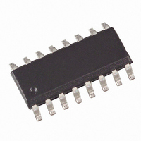
U2102B-MFP Atmel, U2102B-MFP Datasheet - Page 6

U2102B-MFP
Manufacturer Part Number
U2102B-MFP
Description
IC TIMER MULTI IGBT/MOSF 16-SOIC
Manufacturer
Atmel
Type
Timer Controlr
Datasheet
1.U2102B-MFPG3Y.pdf
(19 pages)
Specifications of U2102B-MFP
Frequency - Max
50Hz
Operating Temperature
-10°C ~ 100°C
Mounting Type
Surface Mount
Package / Case
16-SOIC (3.9mm Width)
Frequency-max
50Hz
Lead Free Status / RoHS Status
Contains lead / RoHS non-compliant
Voltage - Supply
-
Output
-
Input
-
6
U2102B
In the case of AC loads, it is necessary to distinguish the power supply purposes of the individ-
ual operating modes. In reverse phase control mode (see
additionally supplied with power via a dropping resistor, since no current flows in pin 16 when
the power switch is switched on. Here, the dropping resistor, R
has therefore only one mains half-wave. R
Figure 3-2.
In two-wire systems, the additional power supply at pin 15 is not possible (see
page
should be as low as the power dissipation allows it. A sufficiently large residual phase angle
must remain in this case to guarantee the device’s supply.
The power supply is simplified if the device is operated as a static zero-voltage switch for AC
loads (see
module is connected directly to the AC line.
R
1max
5, by omitting R
=
0.85
Figure
Power Supply in Reverse Phase Control Mode for AC Loads
V
--------------------------- -
Nmin
2
Voltage
limitation
3-2). All delay times are then twice as long, since the synchronization of the
Sync.
I
–
tot
V
1
Temp.
monit.
S
and diode D
Push
pull
GND
+V
16
15
14
13
S
1
). In this case, the resistor R
1
is then calculated as follows:
R
C
syn
R
1
G
D
R
1
1
IGBT
Figure 3-1 on page
R
sh
1
, is connected to the AC line and
sync
Load
is identical with R
V
5), pin 15 must be
mains
4767B–INDCO–10/05
Figure 3-1 on
1
and


