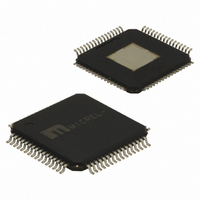
SY89825UHY Micrel Inc, SY89825UHY Datasheet - Page 8

SY89825UHY
Manufacturer Part Number
SY89825UHY
Description
IC CLK DRVR/XLATOR LVDS 64-TQFP
Manufacturer
Micrel Inc
Series
Precision Edge®r
Type
Fanout Buffer (Distribution), Multiplexer , Translatorr
Datasheet
1.SY89825UHY.pdf
(9 pages)
Specifications of SY89825UHY
Number Of Circuits
1
Ratio - Input:output
2:22
Differential - Input:output
Yes/Yes
Input
LVDS, LVPECL
Output
LVPECL
Frequency - Max
2GHz
Voltage - Supply
2.37 V ~ 3.6 V
Operating Temperature
-40°C ~ 85°C
Mounting Type
Surface Mount
Package / Case
64-TQFP Exposed Pad, 64-eTQFP, 64-HTQFP, 64-VQFP
Frequency-max
2GHz
Number Of Clock Inputs
2
Mode Of Operation
Differential
Output Frequency
2000MHz
Output Logic Level
LVPECL
Operating Supply Voltage (min)
2.37V
Operating Supply Voltage (typ)
2.5/3.3V
Operating Supply Voltage (max)
3.6V
Package Type
TQFP EP
Operating Temp Range
-40C to 85C
Operating Temperature Classification
Industrial
Signal Type
LVDS/LVPECL
Mounting
Surface Mount
Pin Count
64
Lead Free Status / RoHS Status
Lead free / RoHS Compliant
Other names
576-2566
SY89825UHY
SY89825UHY
Available stocks
Company
Part Number
Manufacturer
Quantity
Price
Company:
Part Number:
SY89825UHY
Manufacturer:
Micrel Inc
Quantity:
1 839
Company:
Part Number:
SY89825UHY
Manufacturer:
TI
Quantity:
877
Micrel, Inc.
Output Considerations
Be sure to properly terminate all outputs as shown below, or
equivalent. For AC coupled applications
Notes:
1. For +2.5V systems:
Notes:
1. Power-saving alternative to Thevenin termination.
2. Place termination resistors as close to destination inputs as possible.
3. R
4. Precision, low-cost 3-Resistor networks are available from resistor manufacturers such as Thin Film Technology (www.thinfilm.com).
M9999-011907
hbwhelp@micrel.com or (408) 955-1690
LVPECL TERMINATION RECOMMENDATIONS
R1 = 250
R2 = 62.5
b
resistor sets the DC bias voltage equal to V
“source”
, be sure to include a pull
+3.3V
Figure 1. Parallel Termination–Thevenin Equivalent
t
. For +3.3V systems R
+3.3V
Figure 2. Three-Resistor “Y–Termination”
Z
Z
O
O
= 50
= 50
Z = 50
Z = 50
46 to 49
130
82
R1
R2
50
b
= 46 to 49 .
8
+3.3V
down resistor at the output of each driver. The emmiter follower
outputs requires a DC current path to GND. Unused outputs can be
left floating with minimal impact on skew and jitter.
R b
R1
130
R2
82
50
+3.3V
+3.3V
V t = V
CC
“destination”
—2V
Precision Edge
SY89825U
®


