SY10E111LJC Micrel Inc, SY10E111LJC Datasheet - Page 5
SY10E111LJC
Manufacturer Part Number
SY10E111LJC
Description
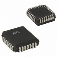
IC CLOCK DRIVER 1:9 DIFF 28-PLCC
Manufacturer
Micrel Inc
Series
100E, Precision Edge®r
Type
Fanout Buffer (Distribution)r
Datasheet
1.SY10E111AJY.pdf
(6 pages)
Specifications of SY10E111LJC
Number Of Circuits
1
Ratio - Input:output
1:9
Differential - Input:output
Yes/Yes
Input
PECL
Output
PECL
Voltage - Supply
3 V ~ 3.8 V
Operating Temperature
0°C ~ 85°C
Mounting Type
Surface Mount
Package / Case
28-LCC (J-Lead)
Number Of Outputs
18
Operating Supply Voltage (max)
-3.8/3.8V
Operating Temp Range
0C to 85C
Propagation Delay Time
0.73ns
Operating Supply Voltage (min)
-3/3V
Mounting
Surface Mount
Pin Count
28
Operating Supply Voltage (typ)
-3.3/3.3V
Package Type
PLCC
Operating Temperature Classification
Commercial
Lead Free Status / RoHS Status
Contains lead / RoHS non-compliant
Frequency-max
-
Lead Free Status / Rohs Status
Not Compliant
Available stocks
Company
Part Number
Manufacturer
Quantity
Price

Part Number:
SY10E111LJC
Manufacturer:
SYNERGY
Quantity:
20 000


Micrel, Inc.
V
Note 1.
Note 2.
Note 3.
Note 4.
Note 5.
Note 6.
M9999-032006
hbwhelp@micrel.com or (408) 955-1690
Symbol
t
t
V
V
t
t
EE
PD
skew
r
f
AC ELECTRICAL CHARACTERISTICS
PP
CMR
= V
EE
Parametric values specified at:
The differential propagation delay is defined as the delay from the crossing points of the differential input signals to the crossing point of the
differential output signals.
The single-ended propagation delay is defined as the delay from the 50% point of the input signal to the 50% point of the output signal.
The within-device skew is defined as the worst case difference between any two similar delay paths within a single device.
V
limited for the E111A/L as a differential input as low as 50mV will still produce full ECL levels at the output.
V
must be such that the peak-to-peak voltage is less than 1.0V and greater than or equal to V
For PECL operation: V
PP
CMR
Propagation Delay to Output
IN (differential), Note 2
IN (single-ended), Note 3
Within-Device Skew, Note 4
Part-to-Part Skew (Diff.)
Minimum Input Swing, Note 5
Common Mode Range, Note 6
Rise/Fall Times
20% to 80%
(Min.) to V
(min) is defined as the minimum input differential voltage which will cause no increase in the propagation delay. The V
is defined as the range within the V
EE
Parameter
(Max.); V
CMR
(max) = V
CC
= GND
CC
5 volt Power Supply Range
3 volt Power Supply Range
– |V
IH
level may vary, with the device still meeting the propagation delay specification. The V
Min. Typ. Max.
–1.5
380
280
250
200
CMR
—
—
T
(max)| and V
A
= -40 C
—
—
—
—
—
—
—
(1)
–0.4
680
780
250
650
75
—
CMR
5
(min) = V
Min. Typ. Max. Min. Typ. Max. Min. Typ. Max. Unit
–1.5
430
330
250
200
—
—
100E111A Series:
10E111A Series
10/100E111L Series:
T
A
= 0 C
—
—
—
—
—
—
—
CC
– |V
–0.4
630
730
200
600
CMR
50
—
(min)|
–1.5
430
330
250
200
PP
—
—
(min).
T
A
= +25 C
—
—
—
—
—
—
—
-4.2V to -5.5V.
-4.75V to -5.5V.
-3.0V to -3.8V.
–0.4
630
730
200
600
50
—
–1.5
430
330
250
200
—
—
T
A
= +85 C
—
—
—
—
—
—
—
PP
Precison Edge
SY100E111A/L
(min) is AC
SY10E111A/L
–0.4
630
730
200
600
50
—
IL
level
mV
ps
ps
ps
V
®
Related parts for SY10E111LJC
Image
Part Number
Description
Manufacturer
Datasheet
Request
R


Part Number:
Description:
Manufacturer:
Micrel Semiconductor
Datasheet:
Part Number:
Description:
Manufacturer:
Micrel Semiconductor
Datasheet:
Part Number:
Description:
Manufacturer:
Micrel Semiconductor
Datasheet:
Part Number:
Description:
Manufacturer:
Micrel Semiconductor
Datasheet:
Part Number:
Description:
Manufacturer:
Micrel Semiconductor
Datasheet:
Part Number:
Description:
Manufacturer:
Micrel Semiconductor
Datasheet:
Part Number:
Description:
Manufacturer:
Micrel Semiconductor
Datasheet:
Part Number:
Description:
Manufacturer:
Micrel Semiconductor
Datasheet:
Part Number:
Description:
Manufacturer:
Micrel Semiconductor
Datasheet:

Part Number:
Description:
Manufacturer:
Micrel Inc
Datasheet:
Part Number:
Description:
Manufacturer:
Micrel Inc
Datasheet:
Part Number:
Description:
Manufacturer:
Micrel Inc
Datasheet:
Part Number:
Description:
Manufacturer:
Micrel Inc
Datasheet:
Part Number:
Description:
Manufacturer:
Micrel Inc
Datasheet: