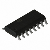
SY10H842ZC Micrel Inc, SY10H842ZC Datasheet - Page 3

SY10H842ZC
Manufacturer Part Number
SY10H842ZC
Description
IC CLK DRIVER 1:4 3.3V 16-SOIC
Manufacturer
Micrel Inc
Series
Precision Edge®r
Type
Fanout Buffer (Distribution)r
Datasheet
1.SY100H842ZH.pdf
(7 pages)
Specifications of SY10H842ZC
Number Of Circuits
1
Ratio - Input:output
1:4
Differential - Input:output
Yes/Yes
Input
PECL
Output
TTL
Frequency - Max
160MHz
Voltage - Supply
4.75 V ~ 5.25 V
Operating Temperature
0°C ~ 85°C
Mounting Type
Surface Mount
Package / Case
16-SOIC (0.300", 7.5mm Width)
Frequency-max
160MHz
Lead Free Status / RoHS Status
Contains lead / RoHS non-compliant
Available stocks
Company
Part Number
Manufacturer
Quantity
Price
Part Number:
SY10H842ZC
Manufacturer:
SYNERGY
Quantity:
20 000
Micrel, Inc.
Note:
1. Permanent device damage may occur if absolute maximum ratings are
Ranges to meet duty cycle requirement: 0 C
V
M9999-032906
hbwhelp@micrel.com or (408) 955-1690
Symbol
V
V
V
V
T
T
T
Symbol
I
I
I
T
Symbol
EE
CCH
CCL
TRUTH TABLE
ABSOLUTE MAXIMUM RATINGS
LEAD
store
A
E
T
I
OUT
exceeded. This is a stress rating only and functional operation is not
implied at conditions other than those detailed in the operational sections
of this data sheet. Exposure to absolute maximum ratlng conditions for
extended periods may affect device reliability.
V
P
P
DC CHARACTERISTICS
= V
(ECL)
W
W
(TTL)
(ECL)
CC
(TTL)
E
AND C
= 5.0V
D
H
X
L
Power Supply Current
Power Supply Current
Power Supply
Voltage
Input Voltage
Lead Temperature
Range (soldering, 20sec)
Storage Temperature
Operating Temperature
Ranges of V
pulse width (HIGH or LOW) at
f
Ranges of V
pulse width (HIGH or LOW) at
f
OUT
OUT
LOAD
5%
40MHz
50MHz
Rating
Parameter
CC
CC
Parameter
EN
H
L
L
and C
and C
L
L
to meet min.
to meet min.
–0.5 to +7.0
–0.5 to +7.0
–65 to +150
0.0 to V
0.0 to V
0 to +85
Value
+260
ECL
TTL
(1)
EE
T
T
A
Q
H
L
L
Min.
—
—
—
85 C. Output duty cycle measured relative to 1.5V.
T
A
Unit
V
V
P
P
C
C
˚C
˚C
˚C
V
V
CC
CC
= 0 C
W
W
L
L
Max.
35
20
25
3
4.875
Min.
4.75
9.0
10
11
15
PIN DESCRIPTION
Pin
10
11
12
13
14
15
16
1
2
3
4
5
6
7
8
9
Min.
T
—
—
—
A
= +25 C
Typ.
5.0
5.0
—
—
—
—
Symbol
Max.
V
EN
G
G
V
G
Q
G
Q
Q
G
Q
V
V
35
20
25
D
D
BB
E
T
T
T
E
T
T
T
0
1
2
3
Max.
5.125
5.25
Min.
50
27
—
—
—
—
—
T
TTL Ground (0V)
Enable Input (PECL)
ECL Ground (0V)
ECL V
ECL Signal Input (Non-inverting)
ECL Signal Input (Inverting)
V
TTL Ground (0V)
Signal Output (TTL)
TTL Ground (0V)
Signal Output (TTL)
TTL V
TTL V
Signal Output (TTL)
TTL Ground (0V)
Signal Output (TTL)
A
BB
= +85 C
Reference Output (PECL)
CC
CC
CC
Max.
Unit
35
20
25
pF
pF
ns
ns
V
V
(+5.0V)
(+5.0V)
(+5.0V)
Description
Unit
mA
mA
All Outputs
All Outputs
Condition
Precision Edge
Total all V
Condition
V
SY100H842
E
SY10H842
Pin
T
pins
®


