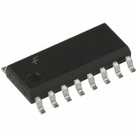
MM74HC4046M Fairchild Semiconductor, MM74HC4046M Datasheet - Page 8

MM74HC4046M
Manufacturer Part Number
MM74HC4046M
Description
IC LOCK LOOP PHASE CMOS 16-SOIC
Manufacturer
Fairchild Semiconductor
Series
74HCr
Type
Phase Lock Loop (PLL)r
Datasheet
1.MM74HC4046M.pdf
(17 pages)
Specifications of MM74HC4046M
Pll
No
Input
CMOS
Output
3-State
Number Of Circuits
1
Ratio - Input:output
1:2
Differential - Input:output
No/No
Frequency - Max
14MHz
Divider/multiplier
No/No
Voltage - Supply
2 V ~ 6 V
Operating Temperature
-40°C ~ 85°C
Mounting Type
Surface Mount
Package / Case
16-SOIC (3.9mm Width)
Frequency-max
14MHz
Supply Voltage (max)
6 V
Supply Voltage (min)
2 V
Maximum Operating Temperature
+ 85 C
Minimum Operating Temperature
- 40 C
Mounting Style
SMD/SMT
Operating Supply Voltage
2 V to 6 V
Number Of Elements
1
Operating Supply Voltage (typ)
2.5/3.3/5V
Operating Temp Range
-40C to 85C
Package Type
SOIC N
Operating Supply Voltage (min)
2V
Operating Supply Voltage (max)
6V
Operating Temperature Classification
Industrial
Pin Count
16
Pll Type
Frequency Synthesis
Frequency
14MHz
Supply Current
600µA
Supply Voltage Range
2V To 6V
Digital Ic Case Style
SOIC
No. Of Pins
16
Operating Temperature Range
-40°C To +85°C
Rohs Compliant
Yes
Lead Free Status / RoHS Status
Lead free / RoHS Compliant
Available stocks
Company
Part Number
Manufacturer
Quantity
Price
Company:
Part Number:
MM74HC4046M
Manufacturer:
FAIRCHIL
Quantity:
222
www.fairchildsemi.com
•Given: f
•Use f
Detailed Circuit Description
VOLTAGE CONTROLLED OSCILLATOR/SOURCE
FOLLOWER
The VCO requires two or three external components to
operate. These are R1, R2, C1. Resistor R1 and capacitor
C1 are selected to determine the center frequency of the
VCO. R1 controls the lock range. As R1’s resistance
decreases the range of f
VCO’s gain increases. As C1 is changed the offset (if used)
of R2, and the center frequency is changed. (See typical
performance curves) R2 can be used to set the offset fre-
quency with 0V at VCO input. If R2 is omitted the VCO
range is from 0Hz. As R2 is decreased the offset frequency
is increased. The effect of R2 is shown in the design infor-
mation table and typical performance curves. By increasing
center frequency vs R1, C
to determine R1 and C1
0
with curve titled
0
R
2
VCO WITHOUT OFFSET
Comparator I
MIN
R2 =
to f
•Given: f
•Calculate f
•Use f
•Calculate f
•Use f
equation f
offset frequency vs R2, C
to determine R2 and C1
the equation f
f
titled f
to determine ratio R2/R1
to obtain R1
o
MAX
f
L
MIN
MAX
/f
MAX
increases. Thus the
o
0
with curve titled
/f
and f
MIN
/f
MIN
MIN
MAX
f
L
R
MIN
2
MAX
L
with curve
from the
/f
vs R2/R1
MIN
f
o
/f
MIN
from
f
L
FIGURE 1.
8
•Given: f
•Calculate f
•Use f
the value of R2 the lock range of the PLL is offset above
0Hz and the gain (Hz/Volt) does not change. In general,
when offset is desired, R2 and C1 should be chosen first,
and then R1 should be chosen to obtain the proper center
frequency.
Internally the resistors set a current in a current mirror as
shown in Figure 1. The mirrored current drives one side of
the capacitor once the capacitor charges up to the thresh-
old of the schmitt trigger the oscillator logic flips the capaci-
tor over and causes the mirror to charge the opposite side
of the capacitor. The output from the internal logic is then
taken to pin 4.
equation f
center frequency vs R1, C
to determine R1 and C1
0
with curve titled
MAX
o
0
R
from the
2
f
MAX
/2
VCO WITH OFFSET
Comparator II & III
•Given: f
•Use f
•Calculate f
•Use f
offset frequency vs R2,
C to determine R2 and C1
titled f
to determine ratio R2/R1
to obtain R1
MIN
MAX
MAX
MIN
/f
with curve titled
MIN
/f
MAX
MIN
R
and f
2
with curve
/f
vs R2/R1
MIN
MAX


