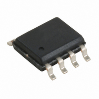
W42C31-03G Cypress Semiconductor Corp, W42C31-03G Datasheet - Page 5

W42C31-03G
Manufacturer Part Number
W42C31-03G
Description
CLOCK EMI REDUCTION SSCG 8-SOIC
Manufacturer
Cypress Semiconductor Corp
Type
Clock/Frequency Synthesizer, Spread Spectrum Clock Generatorr
Datasheet
1.W42C31-03G.pdf
(6 pages)
Specifications of W42C31-03G
Pll
Yes
Input
Crystal
Output
Clock
Number Of Circuits
1
Ratio - Input:output
1:1
Differential - Input:output
No/No
Frequency - Max
33MHz
Divider/multiplier
Yes/No
Voltage - Supply
4.5 V ~ 5.5 V
Operating Temperature
0°C ~ 70°C
Mounting Type
Surface Mount
Package / Case
8-SOIC (3.9mm Width)
Frequency-max
33MHz
Lead Free Status / RoHS Status
Contains lead / RoHS non-compliant
Other names
428-1397
Available stocks
Company
Part Number
Manufacturer
Quantity
Price
Part Number:
W42C31-03G
Manufacturer:
CYPRESS/赛普拉斯
Quantity:
20 000
Application Information
Recommended Circuit Configuration
For optimum performance in system applications the power
supply decoupling scheme shown in Figure 4 should be used.
V
EMI radiation. The 0.1- F decoupling capacitor should be
placed as close to the V
creased trace inductance will negate its decoupling capability.
Ordering Information
Document #: 38-00802
Optional Guard Ring for
XTAL Oscillator Circuitry
W42C31
DD
decoupling is important to both reduce phase jitter and
Ordering Code
G
C1
C2
G
C2
6 pF
G
XTAL1
C1
6 pF
DD
Power Supply Input
(5V)
Freq. Mask
pin as possible, otherwise the in-
XTAL1
Code
03
Figure 5. Recommended Board Layout (2-Layer Board)
G
Figure 4. Recommended Circuit Configuration
FB
Package
GND
Name
G
1
2
3
4
5V System Supply
8-pin Plastic SOIC (150-mil)
C4
Package Type
5
8
7
6
5
The 10- F decoupling capacitor shown should be a tantalum
type. For further EMI protection, the V
made via a ferrite bead, as shown.
The 6-pF XTAL load capacitors can be used to raise the inte-
grated 17-pF capacitance up to a total load of 20 pF on the
crystal.
Recommended Board Layout
Figure 5 shows a recommended 2-layer board layout.
VDD
C3
G
R1
R1
FB
C1, C2 =
FB
Output
G
G
C3 =
C4 =
R1 =
=
=
XTAL load capacitors (optional; use
is not required for operation).
Typical value is 6 pF.
High frequency supply decoupling
capacitor (0.1- µF recommended).
Common supply low frequency
decoupling capacitor (10- µF tantalum
recommended).
Match value to line impedance
Ferrite Bead
Via To GND Plane
C4
10 µF Tantalum
C3
0.1 µF
Clock Output
DD
W42C31-03
connection can be


