1-1740194-2 TE Connectivity, 1-1740194-2 Datasheet - Page 4
1-1740194-2
Manufacturer Part Number
1-1740194-2
Description
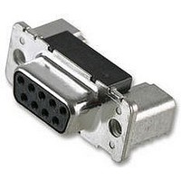
9P HD20 RECEP. HDR UNC4-40 EUROST. SMT
Manufacturer
TE Connectivity
Series
AMPLIMITE HD-20r
Type
D-Subminiaturer
Specifications of 1-1740194-2
Connector Type
D Sub
No. Of Contacts
9
D Sub Shell Size
DA
Connector Body Material
Metal
Gender
Receptacle
Contact Termination
Solder
Length/height, External
12.5mm
Rohs Compliant
Yes
Pitch
2.74 mm
Termination Method
Solder
Mounting
Surface Mount
Body Orientation
Right Angle
Pcb Mounting Orientation
Right Angle
Product Series
HD 20
Mating Connector Lock
With
Mating Connector Lock Type
Threaded Insert, 4-40 UNC
Pcb Mount Retention
With
Shell Type
Front Metal Shell
Shell Size
1
Footprint (mm [in])
7 [.276]
Grounding Indents
Without
Grounding Straps
With
Pcb Mount Style
Surface Mount
Color Code
None
Sealed
No
Profile
Eurostyle - 3.6 mm Installation Height
Color
Black
Shell Material
Steel
Panel Mount Retention
Without
Grounding Clips
Without
Solder Tail Contact Plating
Tin over Nickel
Number Of Positions
9
Pcb Mount Retention Type
Boardlock(s)
Shell Plating
Tin
Contact Plating, Mating Area, Material
Gold (30)
Contact Base Material
CuMg
Connector Style
Receptacle
Ul Flammability Rating
UL 94V-0
Housing Material
PCT - GF
Rohs/elv Compliance
RoHS compliant, ELV compliant
Lead Free Solder Processes
Reflow solder capable to 245°C, Reflow solder capable to 260°C
Rohs/elv Compliance History
Always was RoHS compliant
Available stocks
Company
Part Number
Manufacturer
Quantity
Price
Company:

Part Number:
1-1740194-2
Manufacturer:
TE Connectivity AMP Connectors
Quantity:
4 275


3.6.
NOTE
Qualifikations- und Requalifikationsprüfungen
Temperature life.
Mixed flowing gas.
Component heat resistance to
lead-free reflow soldering.
Solderability, lead - free
NOTE
Examination of product
Termination resistance, dry circuit
Insulation resistance
Dielectric withstanding voltage
Temperature rise vs current
Solderability
Vibration
Physical shock
Durability
Mating force
Unmating force
Thermal shock
Humidity-temperature cycling
Temperature life
Mixed flowing gas
Component heat resistance
Shall meet visual requirements, show no physical damage and shall meet requirements of
additional tests as specified in Test Sequence in Figure 2.
Test or Examination
(a) See paragraph 4.4.A.
(b) Numbers indicate sequence in which tests are performed.
Figure 1 (end)
See note.
See Note
No damage or shrinkage
Solderable area shall have a
minimum of 95% solder coverage
Solderability / Heat resistance
1,9
3,7
1
5
6
4
2
8
4 of 10
1,6
2,5
2
3
4
Figure 2
1,6
2,5
3
3
4
Test Sequence (b)
1,3
Test Group (a)
4
2
1,5
2,4
5
3
1,8
2,6
3,7
6
4
5
IEC 60068 – 2 – 2, Ba
Subject mated connectors to
temperature life at 105°C for
500 hours.
IEC 60068 – 2 -60, Ke / 4
Subject mated connectors to
environmental class III for 20
days. Precondition connectors
with 10 durability cycles.
60068 – 2 – 20, Ta
(Tyco spec. 109-201 / B )
1,3
7
2
1,5
8
3
2
4
108-94000
1,3
9
2
Related parts for 1-1740194-2
Image
Part Number
Description
Manufacturer
Datasheet
Request
R

Part Number:
Description:
CONTACT, MCP 2.8, 17-13AWG
Manufacturer:
TE Connectivity
Datasheet:

Part Number:
Description:
250 FASTON IS
Manufacturer:
TE Connectivity
Datasheet:

Part Number:
Description:
MCP2,8 RECEPTACLE CONTACT
Manufacturer:
TE Connectivity
Datasheet:
Part Number:
Description:
CRIMP, RECEPTACLE
Manufacturer:
TE Connectivity
Datasheet:

Part Number:
Description:
Manufacturer:
TE Connectivity
Datasheet:

Part Number:
Description:
Manufacturer:
TE Connectivity
Datasheet:

Part Number:
Description:
Manufacturer:
TE Connectivity
Datasheet:

Part Number:
Description:
Manufacturer:
TE Connectivity
Datasheet:

Part Number:
Description:
Manufacturer:
TE Connectivity
Datasheet:

Part Number:
Description:
Manufacturer:
TE Connectivity
Datasheet:

Part Number:
Description:
Manufacturer:
TE Connectivity
Datasheet:

Part Number:
Description:
Manufacturer:
TE Connectivity
Datasheet:

Part Number:
Description:
Manufacturer:
TE Connectivity
Datasheet:

Part Number:
Description:
Manufacturer:
TE Connectivity
Datasheet:

Part Number:
Description:
Manufacturer:
TE Connectivity
Datasheet: