1-749814-2 TE Connectivity, 1-749814-2 Datasheet - Page 2
1-749814-2
Manufacturer Part Number
1-749814-2
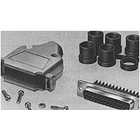
Description
KIT,RCPT,25P,HDE
Manufacturer
TE Connectivity
Specifications of 1-749814-2
Product Type
Connector
Product Series
HDE-20 (IDC)
Termination Method To Wire/cable
Insulation Displacement Crimp (IDC)
Mating Connector Lock
With
Mating Connector Lock Type
Mounting Holes
Shell Size
3
Shell Type
Full Metal Shell
Grounding Indents
Without
Grade
Standard
Cable Clamp Type
One-Piece Quick Snap
Grommets
With
Screws And Retainer Clips
With
Body Material
Polypropylene
Cable Support Gate Material
Polypropylene
Shell Material
Steel
Retainer Clip Material
Stainless Steel
Strain Relief Clip Material
Stainless Steel
Screw Material
Steel
Mounting Screw Material
Steel
Mounting Screw Plating
Zinc
Screw Plating
Zinc
Shielded
Yes
Solder Tail Contact Plating
Tin
Number Of Positions
25
Wire Range (mm² [awg])
0.15 - 0.40 [26-22]
Cable Insulation Diameter (mm [in])
6.48 – 11.94 [0.255 – 0.470]
Cable Exit Angle
180°
Shell Plating
Tin over Copper
Preloaded
Yes
Contact Type
Socket
Contact Base Material
Brass, Phosphor Bronze
Contact Plating, Mating Area, Material
Gold Flash
Contact Size
20
Enclosure
With
Connector Style
Receptacle
Housing Material
Nylon, Polyester GF
Ul Flammability Rating
UL 94V-0
Housing Color
Black
Rohs/elv Compliance
RoHS compliant, ELV compliant
Lead Free Solder Processes
Not relevant for lead free process
Rohs/elv Compliance History
Always was RoHS compliant
Packaging Method
Bulk
Packaging Quantity
100
Available stocks
Company
Part Number
Manufacturer
Quantity
Price
Company:

Part Number:
1-749814-2
Manufacturer:
TE Connectivity AMP Connectors
Quantity:
457


3.4.
3.5.
Examination of Product
Termination Resistance,
Dry Circuit
Dielectric Withstanding Voltage
Insulation Resistance
Temperature Rise
vs Current
Vibration, Random
Physical Shock
Mating Force
Unmating Force
Rev C
Performance and Test Description
The product is designed to meet the electrical, mechanical and environmental performance
requirements specified in Figure 1. All tests are performed at ambient temperature unless otherwise
specified.
Test Requirements and Procedures Summary
Test Description
Meets requirements of product
drawing and Application
Specifications 114-40002 and
114-40003.
30 milliohms maximum.
1 kvac dielectric withstanding voltage,
one minute hold. 1 milliampere
maximum leakage current.
5000 megohms minimum initial. 500
megohms final
Maximum temperature rise at
specified current, 30° C. At a max.
ambient temp. of 70° C
No discontinuities greater than 1
microsecond. See note (a).
No discontinuities greater than 1
microsecond. See note (a).
Pounds maximum
As above.
Size
1
2
3
4
Figure 1 (continued)
Positions
Number
MECHANICAL
ELECTRICAL
Requirement
15
25
37
of
9
Plastics
11.6
2.8
4.7
7.8
All
Metal
Shell
30
33
37
40
Visual, dimensional and functional
per applicable quality inspection
plan.
Subject mated contacts
assembled in housing to 50 mv
open circuit at 100 ma maximum,
see Figure 4; Test Specification
109-6-1.
Test between adjacent contacts of
unmated connector assemblies;
Test Specification109-29-1.
Test between adjacent contacts of
unmated connector assembly;
Test Specification 109-28-1.
Measure temperature rise vs
current;
Test Specification 109-45-1.
Subject mated connectors to 20
G's rms with 100 ma current
applied 20 minutes each axis, see
Figure 3;
Test Specification 109-21-5, test
level F.
Subject mated connector to 50
G's half-sine shock pulses of 11
millisecond duration; 3 shocks in
each direction applied along the 3
mutually perpendicular planes
total 18 shocks, see Figure 3;
Test Specification 109-26-1.
Measure force necessary to mate
connector assembly incorporating
free floating fixtures at a rate of
1.0 inch/minute; Test
Specification 109-42, cond A.
Measure force necessary to
unmate connector assembly at a
rate of 1.0 inch/minute; Test
Specification 109-42, cond A.
Procedure
108-40011
2 of 7
Related parts for 1-749814-2
Image
Part Number
Description
Manufacturer
Datasheet
Request
R

Part Number:
Description:
IC SINGLE 3-IN AND GATE SC-74
Manufacturer:
NXP Semiconductors
Datasheet:
Part Number:
Description:
IC CONFIG MULTI-FUNC GATE SC-74
Manufacturer:
NXP Semiconductors
Datasheet:

Part Number:
Description:
IC SINGLE 2-IN AND GATE SC-74
Manufacturer:
NXP Semiconductors
Datasheet:

Part Number:
Description:
Operational Amplifiers - Op Amps Low-Power Rail-Rail I/O
Manufacturer:
Maxim Integrated
Datasheet:

Part Number:
Description:
Operational Amplifiers - Op Amps OPAMP 20MHZ VFB 120V/US 8CAN MIL
Manufacturer:
Intersil

Part Number:
Description:
Manufacturer:
TE Connectivity
Datasheet:

Part Number:
Description:
INSERT, MALE, SCREW, 16-32
Manufacturer:
TE Connectivity
Datasheet:

Part Number:
Description:
INSERT, FEMALE, SCREW TERM, 16-32WAY
Manufacturer:
TE Connectivity
Datasheet:

Part Number:
Description:
FFC/FPC CONNECTOR, RECEPTACLE 20POS 1ROW
Manufacturer:
TE Connectivity
Datasheet:

Part Number:
Description:
Conn D-Subminiature SKT 9 POS 2.74mm IDT ST Cable Mount 9 Terminal 1 Port
Manufacturer:
TE Connectivity
Datasheet:

Part Number:
Description:
HOUSING, SURFACE MOUNT, SIZE 1
Manufacturer:
TE Connectivity
Datasheet:

Part Number:
Description:
Conn D-Subminiature RCP 9 POS 2.74mm Solder ST Thru-Hole 9 Terminal 1 Port
Manufacturer:
TE Connectivity

Part Number:
Description:
FAST ISO-HUELSE6,3
Manufacturer:
TE Connectivity
Datasheet:
Part Number:
Description:
Manufacturer:
TE Connectivity
Datasheet:
Part Number:
Description:
Manufacturer:
TE Connectivity
Datasheet: