MC1455P1G ON Semiconductor, MC1455P1G Datasheet

IC TIMER/CTRLR MONOLITHIC 8DIP

MC1455P1G

Manufacturer Part Number
MC1455P1G
Description
IC TIMER/CTRLR MONOLITHIC 8DIP
Manufacturer
ON Semiconductor
Type
555 Type, Timer/Oscillator (Single)r
Datasheets

Specifications of MC1455P1G

Voltage - Supply
4.5 V ~ 15 V
Current - Supply
10mA
Operating Temperature
0°C ~ 70°C
Package / Case
8-DIP (0.300", 7.62mm)
Number Of Internal Timers
1
Supply Voltage (max)
16 V
Supply Voltage (min)
4.5 V
Maximum Power Dissipation
625 mW
Maximum Operating Temperature
+ 70 C
Minimum Operating Temperature
0 C
Mounting Style
Through Hole
Circuit Type
MTTL
Current, Supply
3 mA
Logic Function
Timer
Logic Type
CMOS
Number Of Circuits
Single
Package Type
PDIP-8
Temperature, Operating, Range
0 to +70 °C
Voltage, Supply
4.5 to 16 V
Lead Free Status / RoHS Status
Lead free / RoHS Compliant
Frequency
-
Count
-
Lead Free Status / Rohs Status
Lead free / RoHS Compliant
Other names
MC1455P1GOS
MC1455, MC1455B,
NCV1455B
Timers
capable of producing accurate time delays or oscillation. Additional
terminals are provided for triggering or resetting if desired. In the time
delay mode, time is precisely controlled by one external resistor and
capacitor. For astable operation as an oscillator, the free−running
frequency and the duty cycle are both accurately controlled with two
external resistors and one capacitor. The circuit may be triggered and
reset on falling waveforms, and the output structure can source or sink
up to 200 mA or drive MTTL circuits.
Features
© Semiconductor Components Industries, LLC, 2006
t = 1.1; R and C = 22 sec
Time delay (t) is variable by
changing R and C (see Figure 16).
The MC1455 monolithic timing circuit is a highly stable controller
Control Voltage
Direct Replacement for NE555 Timers
Timing from Microseconds through Hours
Operates in Both Astable and Monostable Modes
Adjustable Duty Cycle
High Current Output Can Source or Sink 200 mA
Output Can Drive MTTL
Temperature Stability of 0.005% per °C
Normally ON or Normally OFF Output
Pb−Free Packages are Available
0.1 mF
Figure 1. 22 Second Solid State Time Delay Relay Circuit
Threshold
10 k
Trigger
0.01 mF
Figure 2. Representative Block Diagram
6
5
2
5
5 k
5 k
5 k
V
CC
4
2
8
3
MC1455
+
Comp
+
Comp
GND
A
B
8
1
1
1.0 k
6
7
1.0 mF
R
S
R
Reset
Inhibit/
Reset
Flop
Flip
1N4740
20 M
C
4
Q
−10 V
G
MT2
3.5 k
250 V
MT1
+
10 mF
Load
1N4003
7
3
Discharge
Output
1
Test circuit for measuring DC parameters (to set output and measure
parameters):
a) When V
b) When V
c) When V
c)
c)
high, apply Reset voltage, and test for current flowing into Pin 7.
When Reset is not in use, it should be tied to V
0.01 mF
V
O
See detailed ordering and shipping information in the package
dimensions section on page 9 of this data sheet.
8
+
S
S
O
8
w 2/3 V
v 1/3 V
is low, Pin 7 sinks current. To test for Reset, set V
1
I
I
Control
Voltage
Sink
Source
Figure 3. General Test Circuit
Output
1
V
5
3
R
ORDERING INFORMATION
Reset
x
yyy
A
L
Y, YY
W, WW = Work Week
G or G
CC
CC
, V
, V
O
O
MC1455
GND
4
1
is high.
is low.
CASE 751
P1 SUFFIX
D SUFFIX
CASE 626
= B or V
= BP1 or P1
= Assembly Location
= Wafer Lot
= Year
= Pb−Free Package
SOIC−8
PDIP−8
V
2
8
CC
Trigger
Publication Order Number:
Discharge
7
Threshold
6
I
CC
I
th
8
1
700
8
1
DIAGRAMS
CC
MC1455yyy
2.0 k
MARKING
V
.
CC
YYWWG
1455x
ALYW
V
MC1455/D
S
G
AWL
O

Related parts for MC1455P1G

MC1455P1G Summary of contents

Page 1

MC1455, MC1455B, NCV1455B Timers The MC1455 monolithic timing circuit is a highly stable controller capable of producing accurate time delays or oscillation. Additional terminals are provided for triggering or resetting if desired. In the time delay mode, time is precisely ...

Page 2

MAXIMUM RATINGS (T = +25°C, unless otherwise noted.) A Rating Power Supply Voltage Discharge Current (Pin 7) Power Dissipation (Package Limitation) P1 Suffix, Plastic Package Derate above T = +25° Suffix, Plastic Package Derate above T = +25°C ...

Page 3

... ORDERING INFORMATION Device Operating Temperature Range MC1455P1 MC1455P1G MC1455D MC1455DG MC1455DR2 MC1455DR2G MC1455BD MC1455BDG MC1455BDR2 T MC1455BDR2G MC1455BP1 MC1455BP1G NCV1455BDR2* T NCV1455BDR2G* †For information on tape and reel specifications, including part orientation and tape sizes, please refer to our Tape and Reel Packaging Specifications Brochure, BRD8011/D. ...
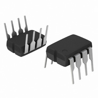
Page 4

F −A− NOTE 2 C −T− N SEATING PLANE 0.13 (0.005) M MC1455, MC1455B, NCV1455B PACKAGE DIMENSIONS PDIP−8 P1 SUFFIX CASE 626−05 ISSUE ...

Related keywords