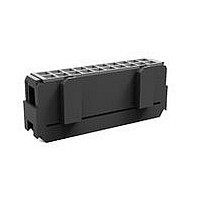
1658624-9 TE Connectivity, 1658624-9 Datasheet - Page 3

1658624-9
Manufacturer Part Number
1658624-9
Description
40 NOVO DUAL 30DP, LEAD FREE
Manufacturer
TE Connectivity
Series
NOVOr
Specifications of 1658624-9
Product Line
AMP-LATCH
Connector Type
Connector Assembly
Shrouded
No
Termination Method To Wire/cable
IDC
Ul File Number
E28476
Csa File Number
LR 7189
Contact - Rated Current (a)
1
Operating Voltage Reference
AC
Operating Voltage (vac)
250
Wire/cable Size (awg)
26 – 28
Wire/cable Size (mm²)
0.08 – 0.15
Wire/cable Size (cma)
158 – 296
Profile Height (y-axis) (mm [in])
15.16 [0.5968]
Number Of Positions
40
Centerline (mm [in])
2.54 [0.100]
Row-to-row Spacing (mm [in])
2.54 [0.100]
Number Of Rows
2
Length (x-axis) (mm [in])
55.37 [2.1799]
Width (z-axis) (mm [in])
7.49 [0.2949]
Contact Design
Tuning Fork
Contact Type
Socket
Contact Base Material
Phosphor Bronze
Contact Plating, Mating Area, Material
Gold or Palladium Nickel or Performance Based
Contact Plating, Mating Area, Thickness (µm [?in])
0.762 [30]
Connector Style
Receptacle
Mating Alignment
With
Mating Alignment Type
Polarization
Housing Color
Black
Ul Flammability Rating
UL 94V-0
Rohs/elv Compliance
RoHS compliant, ELV compliant
Lead Free Solder Processes
Not relevant for lead free process
Rohs/elv Compliance History
Always was RoHS compliant
Agency/standard
UL, CSA
Ul Rating
Recognized
Ul Voltage Rating (vac)
250
Operating Temperature (°c [°f])
-65 – +105 [-85 – +221]
Applies To
Wire/Cable
Accepts Wire Insulation Diameter, Range (mm [in])
0.787 – 0.94 [0.031 – 0.037]
Application Use
Wire-to-Board
Contact Transmits (typical Application)
Signal (Data)
Packaging Method
Tube
Physical shock.
Connector m ating force.
Connector unm ating force.
Durability.
Therm al shock.
Hum idity/tem perature cycling.
Mixed flowing gas.
Rev D
Test Description
No discontinuity greater than 1
m icrosecond.
See Note (a).
12 ounces m axim um per contact.
1.5 ounces m inim um per contact.
Term ination resistance, dry circuit.
See Note (b).
Term ination resistance, dry circuit.
Insulation resistance.
Dielectric withstanding voltage.
See Note (c).
See Note (d).
Insulation resistance.
Dielectric withstanding voltage.
See Note (a).
Term ination resistance, dry circuit.
See Note (a).
Figure 1 (continued)
ENVIRONMENTAL
Requirem ent
TE Spec 109-42, Condition A.
TE Spec 109-42, Condition A.
TE Spec 109-26-9.
Subject rigid m ount wired and
m ated connectors to 100 Gs
sawtooth shock pulses of 6
m illiseconds duration. Three shocks
in each direction applied along 3
m utually perpendicular planes, 18
shocks total.
Measure force necessary to m ate
connector for first m ating. Calculate
m ating force per contact by dividing
m ating force by num ber of contacts.
Measure force necessary to unm ate
connector after first m ating.
Calculate unm ating force per
contact by dividing unm ating force
by num ber of contacts.
TE Spec 109-27.
Mate and unm ate 15 ìin gold plated
connectors or equivalent 3 ìin gold
over 12 ìin palladium nickel for 75
cycles. Mate and unm ate 30 ìin
gold plated connectors or equivalent
3 ìin gold over 27 ìin palladium
nickel for 150 cycles at m axim um
rate of 150 cycles per hour.
TE Spec 109-22.
Subject unwired and unm ated
connectors of Test Group 2 and
wired and m ated connectors of Test
Group 4 to 5 cycles between -65
and 105°C.
TE Spec 109-23, Condition B,
Method III less step 7(b).
Subject m ated and unterm inated
connectors to 10 days
hum idity/tem perature cycling at 25
to 65°C and 80 to 98% RH, 5 cold
shocks at -10°C.
TE Spec 109-85-3.
Subject m ated connectors to
environm ental class III for 20 days.
Procedure
108-40000
3 of 6


