1711160-2 TE Connectivity, 1711160-2 Datasheet
1711160-2
Specifications of 1711160-2


Related parts for 1711160-2


1711160-2 Summary of contents
Page 1
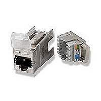
... SL Jack 108-93044 411-93007 & 411-93014 C-1711160 / C-1711342 C-1711295 / C-1711343 1711160-2 / 1711342-2 1711295-2 / 1711343-2 501-93032 * AMP, AMP NETCONNECT, Tyco Electronics, TE Logo and AMP-TWIST are trade marks of TE Connectivity. Rev. B: Correcting PN on 2.1 table. 3.7 test requirements: Clarifying electrical requirement for Insulation resistance and adding Transfer Impedance and Coupling test. ...
Page 2
... Detail Specification for 8-way, shielded free and fixed connectors with common mating features, with assessed quality Generic cabling systems- Specification for the testing of balanced communication cabling in accordance with ISO/IEC 11801. Part 1: Installed cabling 2009): UL Report/File E81956. PN’s related: 1711160-2, 0. AWG AWG 0.80 - 1.60 5.0 - 9.0 150 Vac max ...
Page 3
Test Requirements and Procedures Summary Test Description Examination of product Meets requirements of product drawing Input-output Resistance ISO/IEC 11801. 2 200 m maximum initial and final. Shield resistance ISO/IEC 11801. 2 100 m maximum initial and final. Input-output Resistance ...
Page 4
ACR-F Class E requirements according to Amend ISO/IEC 11801 2nd Ed. PS ACR-F Class E requirements according to Amend ISO/IEC 11801 2nd Ed. Propagation delay Class E requirements according to Amend ISO/IEC 11801 2nd ...
Page 5
Durability repeated, See note IDC-wire interface Panel housing retention 90 Nw minimum Front/rear housing retention 90 Nw minimum Thermal shock. See note Jack-plug interface and IDC- wire interface Humidity-temperature cycling. See note Jack-plug interface and IDC- wire interface Humidity, steady ...
Page 6
Product Qualification and Re-qualification Test Sequence. Examination of product ELECTRICAL Input-output Resistance Shield Contact resistance Input-output Resistance unbalance Current carrying capacity Insulation resistance Voltage proof Wire map & Shield Continuity MECHANICAL Vibration, Jack-plug interface and IDC-wire interface Durability, Jack-plug ...
Page 7
Delay Skew Transfer Impedance Coupling Attenuation NOTE (a) (b) (c) Minimum number of samples required per each test group to be terminated with adequate cable. Test AWG 22 / group Solid ...
Page 8
QUALITY ASSURANCE PROVISIONS 4.1. Qualification Testing A. Sample Selection Samples (Jacks) shall be prepared in accordance with applicable Instruction Sheets (Refer to Tyco Electronics documents, see paragraph 2.1) and shall be selected at random from current production. All test ...
Page 9
Cable Metal braid Input/Output and shield resistance measurement points as shown Resistance due to wire lengths and cable shielding shall be subtracted from all readings. NOTE Termination resistance of this assembly consists of plug to jack contact resistance plus printed ...