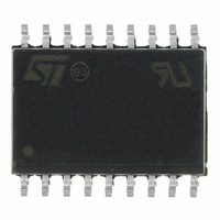
M41T83RMY6E STMicroelectronics, M41T83RMY6E Datasheet - Page 42

M41T83RMY6E
Manufacturer Part Number
M41T83RMY6E
Description
IC RTC SERIAL W/BATT SW SOX18
Manufacturer
STMicroelectronics
Type
Clock/Calendar/Alarmr
Datasheet
1.M41T82SM6F.pdf
(61 pages)
Specifications of M41T83RMY6E
Memory Size
32B
Time Format
HH:MM:SS:hh (24 hr)
Date Format
YY-MM-DD-dd
Interface
I²C, 2-Wire Serial
Voltage - Supply
2.7 V ~ 5.5 V
Operating Temperature
-40°C ~ 85°C
Mounting Type
Surface Mount
Package / Case
18-SOX, 18-SOIC with Crystal (7.5mm Width)
Lead Free Status / RoHS Status
Lead free / RoHS Compliant
Available stocks
Company
Part Number
Manufacturer
Quantity
Price
Clock operation
3.14.1
Table 15.
1. OUT is bit 7 of register 08h (digital calibration).
2. FT is bit 6 of register 08h (digital calibration).
3. A1IE is bit 7 of register 0Ah (alarm 1, month).
4. OFIE is bit 7 of register 09h (watchdog).
5. TIE is bit 5 of register 11h (timer control).
6. The watchdog is controlled by register 09h (watchdog).
42/61
OUT
0
0
1
1
x
(1)
The timer, oscillator fail detect circuit, alarm 1, and watchdog are ORed together as the
primary interrupt sources. The frequency test signal, FT, is used to enable a 512 Hz output
on the IRQ1/FT/OUT pin for calibrating the RTC. When not used as an interrupt or
frequency test output, the pin can be used as a discrete logic output controlled by the OUT
bit. The ABE bit is used to enable interrupts during backup mode.
Operating on V
watchdog are disabled, and the only interrupt sources are alarm 1 and the oscillator fail
detect circuit.
Active mode operation on V
On V
Priority for IRQ1/FT/OUT pin when operating on V
When OUT is 0 and FT is 0, the pin will be 0 regardless of whether any interrupts are
enabled.
When FT is a 1, the 512 Hz signal will be output if OUT is 0 or if no interrupts are enabled.
The interrupt sources control the pin when OUT is 1 and one or more of the interrupts are
enabled.
If OUT is 1, FT is 0 and no interrupts are enabled, then the pin will be 1.
FT
0
1
1
0
x
CC
(2)
, the operation of the output circuit is as shown in
+ watchdog
+ OFIE
running
+ TIE
A1IE
CC
, all four interrupt sources are available. During backup, the timer and
0
1
0
x
x
(3)
(5)
(4)
(6)
512 Hz
Doc ID 12578 Rev 12
IRQ
Pin
0
1
CC
When OUT is 0 and FT is not enabled, OUT dominates
and none of the interrupt sources have any effect.
When FT = 1 and OUT = 1 and no interrupts are enabled,
the output will be the 512 Hz frequency test (FT) signal.
When one or more interrupts are enabled, and OUT is a 1,
the pin stays high until one of the interrupts is asserted.
When OUT is 1, FT is 0 and no interrupts are enabled, the
pin is high.
CC
Table
Comment
15.
M41T82-M41T83


