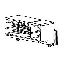
2-638211-6 TE Connectivity, 2-638211-6 Datasheet

2-638211-6
Specifications of 2-638211-6
Related parts for 2-638211-6
2-638211-6 Summary of contents
Page 1
... JASO D7101: Test Methods for Plastic Molded Parts ! JIS C3406: Low Voltage Wires and Cables for Automobiles ! JIS D0203: Method of Moisture, Rain and Spray Test for Automobile Parts ! JIS D0204: Method of High and Low Temperature Test for Automobile Parts ! JIS D1601: Vibration Testing Method for Automobile Parts ...
Page 2
... Ratings Temperature: -30 to 105 ! 3.4. Performance and Test Description Product is designed to meet the electrical, mechanical and environmental performance requirements specified in Figure 2. Unless otherwise specified, all tests shall be performed at room temperature. 3.5. Test Requirements and Procedures Summary Para Test Item 3.5.1 Confirmation of Product 3 ...
Page 3
... III: 0.98 N minimum for silver plating; 0.69 N minimum for gold plating. 10 position maximum. 12 position maximum. 16 position maximum. 22 position: 88.3 N maximum. 26 position: 98.1 N maximum. 10 position maximum. 12 position maximum. 16 position maximum. 22 position: 88.3 N maximum. 26 position: 98.1 N maximum minimum. Figure 1 (continued) 108-5342-3 ...
Page 4
... Contact Retention Force, Secondary Lock 3.5.19 Crimp Tensile Strength 3.5.20 Durability, Repeated Mating/Unmating 3.5.21 Resistance to “Kojiri” 3.5.22 Solderability 3.5.23 Handling Ergonomics 3.5.24 Double Lock Plate Locking Strength 3.5.25 Thermal Shock Rev A Requirement 9.8 N maximum per contact minimum minimum. Wire Size ...
Page 5
... Mated/unmated connector 95% RH hours. / AMP Spec 109-5105. SO gas: 10 ppm, 95% RH hours. / AMP Spec 109-5107. 120 C , 120 hours. / AMP Spec 109-5104. -50 ± 120 hours. / AMP Spec 109-5108. Subject JIS R5210 cement blow of 1.5 kg per 10 seconds in 15 minute intervals for 90 minutes. AMP Spec 109-5110 ...
Page 6
... Double Lock Plate Locking Strength Thermal Shock Humidity, Steady State Industrial Gas Temperature Life, Heat Aging Resistance to Cold Dust Bombardment (a) Numbers indicate sequence in which tests are performed. Rev A Test Group Test Sequence ( 1,19 1,11 1, 3,5,7 3,6,8 3,6,8 3,6,8,10 2,7,9,14 3,6 2,10 2, Figure 2 108-5342 ...
Page 7
... From the measured readings, deduct the resistance of the 150 mm long wire used for termination. When testing for rated current measurement, apply 12 volts DC, 1 ampere to the circuit. For obtaining uniformity of the current density on the probing points Y Y’, apply soldering on the probing points prior to testing. ...
Page 8
... Wire Size (mm ( • ( max Wire Size 2 (mm ) 0.3 0.5 0.85 1.25 2.0 Rev A Maximum Allowable Current (I maximum Allowable Current (DC A) 0.3 0.5 0.85 1.25 2.0 Figure 6 Reduction Coefficient (Kd) Number of Reduction Energized Contacts Coefficient 1 1 2-3 0.75 4-5 0.6 6-8 0.55 9-12 ...
Page 9
... Rev A Figure 9 Figure 10 Figure 11 108-5342 ...
Page 10
... Rev A APPENDIX 108-5342 ...
Page 11
... Hybrid I/O connector MK-II 26 position plug housing assembly 178888 .040/.070 Hybrid I/O connector MK-II 26 position 3 row plug housing assembly 178897 .040/.070 Hybrid I/O connector MK-II 26 position 3 row low profile plug housing assembly 175571 .040/.070 Hybrid I/O connector 26 position cap housing assembly 178811 ...
Page 12
... S receptacle contact (pre-tin) 175266 .040II S receptacle contact (selective gold) 175268 .070II S receptacle contact (pre-tin) 175275 .070II S receptacle contact (selective gold) 175269 .070II M receptacle contact (pre-tin) 175276 .070II M receptacle contact (selective gold) 1318629 .070III ML receptacle contact (pre-tin) Rev A Product Description 108-5342 ...


