DS1554WP-120 Maxim Integrated Products, DS1554WP-120 Datasheet - Page 9
DS1554WP-120
Manufacturer Part Number
DS1554WP-120
Description
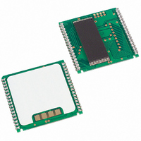
IC RTC RAM Y2K 3.3V 120NS 34-PCM
Manufacturer
Maxim Integrated Products
Type
Clock/Calendar/NVSRAM/Y2Kr
Datasheet
1.DS1554P-70.pdf
(18 pages)
Specifications of DS1554WP-120
Memory Size
256K (32K x 8)
Time Format
HH:MM:SS (24 hr)
Date Format
YY-MM-DD-dd
Interface
Parallel
Voltage - Supply
3 V ~ 3.6 V
Operating Temperature
0°C ~ 70°C
Mounting Type
Surface Mount
Package / Case
34-PowerCap™ Module
Lead Free Status / RoHS Status
Contains lead / RoHS non-compliant
Available stocks
Company
Part Number
Manufacturer
Quantity
Price

Company:
Part Number:
DS1554WP-120IND+
Manufacturer:
Maxim Integrated Products
Quantity:
135
Company:
Part Number:
DS1554WP-120IND+
Manufacturer:
Maxim
Quantity:
603


Table 3. Alarm Mask Bits
When the RTC Register values match Alarm Register settings, the Alarm Flag bit (AF) is set to a 1. If
Alarm Flag Enable (AE) is also set to a 1, the alarm condition activates the IRQ/FT pin. The IRQ/FT
signal is cleared by a read or write to the Flags Register (Address 7FF0h) as shown in Figure 2 and 3.
When CE is active, the IRQ/FT signal may be cleared by having the address stable for as short as 15 ns
and either OE or WE active, but is not guaranteed to be cleared unless t
also cleared by a read or write to the Flags Register but the flag will not change states until the end of the
read/write cycle and the IRQ/FT signal has been cleared.
Figure 2. Clearing IRQ Waveforms
Figure 3. Clearing IRQ Waveforms
The IRQ/FT pin can also be activated in the battery-backed mode. The IRQ/FT will go low if an alarm
occurs and both ABE and AE are set. The ABE and AE bits are cleared during the power-up transition,
however an alarm generated during power-up will set AF. Therefore, the AF bit can be read after system
power-up to determine if an alarm was generated during the power-up sequence. Figure 4 illustrates alarm
timing during the battery-backup mode and power-up states.
AM4
1
1
1
1
0
CE,
AM3
CE=0
1
1
1
0
0
0V
AM2
1
1
0
0
0
AM1
1
0
0
0
0
ALARM RATE
Once per second
When seconds match
When minutes and seconds match
When hours, minutes, and seconds match
When date, hours, minutes, and seconds match
DS1554 256k, Nonvolatile, Y2K-Compliant Timekeeping RAM
9 of 18
RC
is fulfilled. The alarm flag is
Related parts for DS1554WP-120
Image
Part Number
Description
Manufacturer
Datasheet
Request
R

Part Number:
Description:
IC RTC RAM Y2K 3.3V 120NS 34-PCM
Manufacturer:
Maxim Integrated Products
Datasheet:
Part Number:
Description:
IC RTC RAM Y2K 3.3V 120NS 34-PCM
Manufacturer:
Maxim Integrated Products
Datasheet:

Part Number:
Description:
Real Time Clock
Manufacturer:
Maxim Integrated Products
Datasheet:

Part Number:
Description:
IC RTC RAM Y2K 3.3V 120NS 32EDIP
Manufacturer:
Maxim Integrated Products
Datasheet:
Part Number:
Description:
IC RTC RAM Y2K 3.3V 120NS 32EDIP
Manufacturer:
Maxim Integrated Products
Datasheet:
Part Number:
Description:
IC RTC RAM Y2K 3.3V 120NS 32EDIP
Manufacturer:
Maxim Integrated Products
Datasheet:
Part Number:
Description:
IC RTC RAM Y2K 3.3V 120NS 32EDIP
Manufacturer:
Maxim Integrated Products
Datasheet:
Part Number:
Description:
MAX7528KCWPMaxim Integrated Products [CMOS Dual 8-Bit Buffered Multiplying DACs]
Manufacturer:
Maxim Integrated Products
Datasheet:
Part Number:
Description:
Single +5V, fully integrated, 1.25Gbps laser diode driver.
Manufacturer:
Maxim Integrated Products
Datasheet:
Part Number:
Description:
Single +5V, fully integrated, 155Mbps laser diode driver.
Manufacturer:
Maxim Integrated Products
Datasheet:
Part Number:
Description:
VRD11/VRD10, K8 Rev F 2/3/4-Phase PWM Controllers with Integrated Dual MOSFET Drivers
Manufacturer:
Maxim Integrated Products
Datasheet:
Part Number:
Description:
Highly Integrated Level 2 SMBus Battery Chargers
Manufacturer:
Maxim Integrated Products
Datasheet:
Part Number:
Description:
Current Monitor and Accumulator with Integrated Sense Resistor; ; Temperature Range: -40°C to +85°C
Manufacturer:
Maxim Integrated Products
Part Number:
Description:
TSSOP 14/A°/RS-485 Transceivers with Integrated 100O/120O Termination Resis
Manufacturer:
Maxim Integrated Products
Part Number:
Description:
TSSOP 14/A°/RS-485 Transceivers with Integrated 100O/120O Termination Resis
Manufacturer:
Maxim Integrated Products