DS1553P-85+ Maxim Integrated Products, DS1553P-85+ Datasheet - Page 10
DS1553P-85+
Manufacturer Part Number
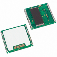
DS1553P-85+
Description
IC RTC RAM Y2K 5V 85NS 34-PCM
Manufacturer
Maxim Integrated Products
Type
Clock/Calendar/NVSRAM/Y2Kr
Datasheet
1.DS1553WP-120.pdf
(20 pages)
Specifications of DS1553P-85+
Memory Size
64K (8K x 8)
Time Format
HH:MM:SS (24 hr)
Date Format
YY-MM-DD-dd
Interface
Parallel
Voltage - Supply
4.5 V ~ 5.5 V
Operating Temperature
0°C ~ 70°C
Mounting Type
Surface Mount
Package / Case
34-PowerCap™ Module
Lead Free Status / RoHS Status
Lead free / RoHS Compliant


DS1553 64kB, Nonvolatile, Year-2000-Compliant Timekeeping RAM
USING THE WATCHDOG TIMER
The watchdog timer can be used to detect an out-of-control processor. The user programs the watchdog
timer by setting the desired amount of timeout into the 8-bit Watchdog register (Address 1FF7h). The five
Watchdog register bits BMB4–BMB0 store a binary multiplier and the two lower-order bits
RB1–RB0 select the resolution, where 00 = 1/16 second, 01 = 1/4 second, 10 = 1 second, and
11 = 4 seconds. The watchdog timeout value is then determined by the multiplication of the 5-bit
multiplier value with the 2-bit resolution value. (For example: writing 00001110 in the Watchdog register
= 3 x 1 second or 3 seconds.) If the processor does not reset the timer within the specified period, the
Watchdog Flag (WF) is set and a processor interrupt is generated and stays active until either the
Watchdog Flag (WF) is read or the Watchdog register (1FF7) is read or written.
The most significant bit of the Watchdog register is the Watchdog Steering Bit (WDS). When set to 0, the
watchdog activates the
/FT output when the watchdog times out.
IRQ
When WDS is set to 1, the watchdog outputs a negative pulse on the
output for 40ms to 200ms. The
RST
Watchdog register (1FF7) and the FT bit are reset to 0 at the end of a watchdog timeout when the WDS
bit is set to 1.
The watchdog timer resets when the processor performs a read or write of the Watchdog register. The
timeout period then starts over. Writing a value of 00h to the Watchdog register disables the watchdog
timer. The watchdog function is automatically disabled upon power-up and the Watchdog register is
cleared. If the watchdog function is set to output to the
/FT output and the frequency test function is
IRQ
activated, the watchdog function prevails and the frequency test function is denied.
POWER-ON DEFAULT STATES
Upon application of power to the device, the following register bits are set to 0:
WDS = 0, BMB0–BMB4 = 0, RB0–RB1 = 0, AE = 0, and ABE = 0.
10 of 20
Related parts for DS1553P-85+
Image
Part Number
Description
Manufacturer
Datasheet
Request
R

Part Number:
Description:
IC RTC RAM Y2K 5V 100NS 34-PCM
Manufacturer:
Maxim Integrated Products
Datasheet:
Part Number:
Description:
IC RTC RAM Y2K 5V 70NS 34-PCM
Manufacturer:
Maxim Integrated Products
Datasheet:

Part Number:
Description:
Real Time Clock
Manufacturer:
Maxim Integrated Products
Datasheet:
Part Number:
Description:
Real Time Clock
Manufacturer:
Maxim Integrated Products
Datasheet:

Part Number:
Description:
64kb, Nonvolatile, Year-2000-compliant Timekeeping Ram
Manufacturer:
Maxim Integrated Products, Inc.
Datasheet:
Part Number:
Description:
64K NV Y2KC Real Time Clocks RAM
Manufacturer:
Maxim Integrated Products
Datasheet:

Part Number:
Description:
IC RTC RAM Y2K 5V 85NS 28-EDIP
Manufacturer:
Maxim Integrated Products
Datasheet:
Part Number:
Description:
IC RTC RAM Y2K 5V 100NS 28-EDIP
Manufacturer:
Maxim Integrated Products
Datasheet:
Part Number:
Description:
IC RTC RAM Y2K 5V 100NS 28-EDIP
Manufacturer:
Maxim Integrated Products
Datasheet:
Part Number:
Description:
IC RTC RAM Y2K 5V 70NS 28-EDIP
Manufacturer:
Maxim Integrated Products
Datasheet:
Part Number:
Description:
Real Time Clock
Manufacturer:
Maxim Integrated Products
Datasheet:
Part Number:
Description:
MAX7528KCWPMaxim Integrated Products [CMOS Dual 8-Bit Buffered Multiplying DACs]
Manufacturer:
Maxim Integrated Products
Datasheet:
Part Number:
Description:
Single +5V, fully integrated, 1.25Gbps laser diode driver.
Manufacturer:
Maxim Integrated Products
Datasheet:
Part Number:
Description:
Single +5V, fully integrated, 155Mbps laser diode driver.
Manufacturer:
Maxim Integrated Products
Datasheet:
Part Number:
Description:
VRD11/VRD10, K8 Rev F 2/3/4-Phase PWM Controllers with Integrated Dual MOSFET Drivers
Manufacturer:
Maxim Integrated Products
Datasheet: