DS1557WP-120+ Maxim Integrated Products, DS1557WP-120+ Datasheet - Page 6
DS1557WP-120+
Manufacturer Part Number
DS1557WP-120+
Description
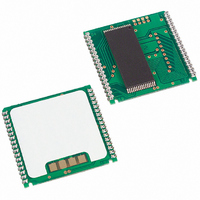
IC RTC RAM Y2K 3.3V 120NS 34PCM
Manufacturer
Maxim Integrated Products
Type
Clock/Calendar/NVSRAM/Y2Kr
Datasheet
1.DS1557P-70.pdf
(17 pages)
Specifications of DS1557WP-120+
Memory Size
4M (512K x 8)
Time Format
HH:MM:SS (24 hr)
Date Format
YY-MM-DD-dd
Interface
Parallel
Voltage - Supply
3 V ~ 3.6 V
Operating Temperature
0°C ~ 70°C
Mounting Type
Surface Mount
Package / Case
34-PowerCap™ Module
Lead Free Status / RoHS Status
Lead free / RoHS Compliant


DS1557 4Meg, Nonvolatile, Y2K-Compliant Timekeeping RAM
CLOCK OSCILLATOR CONTROL
The clock oscillator may be stopped at any time. To increase the shelf life of the backup lithium battery
source, the oscillator can be turned off to minimize current drain from the battery. The OSC bit is the
MSB of the Seconds Register (B7 of 7FFF9h). Setting it to a 1 stops the oscillator, setting to a 0 starts the
oscillator. The DS1557 is shipped from Maxim with the clock oscillator turned off, OSC bit set to a 1.
READING THE CLOCK
When reading the RTC data, it is recommended to halt updates to the external set of double-buffered
RTC Registers. This puts the external registers into a static state allowing data to be read without register
values changing during the read process. Normal updates to the internal registers continue while in this
state. External updates are halted when a 1 is written into the read bit, B6 of the Control Register
(7FFF8h). As long as a 1 remains in the Control Register read bit, updating is halted. After a halt is
issued, the registers reflect the RTC count (day, date, and time) that was current at the moment the halt
command was issued. Normal updates to the external set of registers will resume within 1 second after
the read bit is set to a 0 for a minimum of 500 s. The read bit must be a zero for a minimum of 500 s to
ensure the external registers will be updated.
SETTING THE CLOCK
The MSB bit, B7, of the Control Register is the write bit. Setting the write bit to a 1, like the read bit,
halts updates to the DS1557 (7FFF8h-7FFFFh) registers. After setting the write bit to a 1, RTC registers
can be loaded with the desired RTC count (day, date, and time) in 24-hour BCD format. Setting the write
bit to a 0 then transfers the values written to the internal RTC registers and allows normal operation to
resume.
CLOCK ACCURACY
The DS1557 and DS9034PCX are each individually tested for accuracy. Once mounted together, the
module will typically keep time accuracy to within 1.53 minutes per month (35 ppm) at 25°C and does
not require additional calibration. For this reason, methods of field clock calibration are not available and
not necessary. The electrical environment also affects clock accuracy and caution should be taken to
place the RTC in the lowest-level EMI section of the PC board layout. For additional information, refer
to Application Note 58.
FREQUENCY TEST MODE
The DS1557 frequency test mode uses the open drain IRQ/FT output. With the oscillator running, the
IRQ/FT output will toggle at 512 Hz when the FT bit is a 1, the Alarm Flag Enable bit (AE) is a 0, and
the Watchdog Steering bit (WDS) is a 1 or the Watchdog Register is reset (Register 7FFF7h = 00h). The
IRQ/FT output and the frequency test mode can be used as a measure of the actual frequency of the
32.768kHz RTC oscillator. The IRQ/FT pin is an open-drain output that requires a pullup resistor for
proper operation. The FT bit is cleared to a 0 on power-up.
6 of 17
Related parts for DS1557WP-120+
Image
Part Number
Description
Manufacturer
Datasheet
Request
R

Part Number:
Description:
IC RTC RAM Y2K 3.3V 120NS 34PCM
Manufacturer:
Maxim Integrated Products
Datasheet:
Part Number:
Description:
IC RTC RAM Y2K 3.3V 120NS 34PCM
Manufacturer:
Maxim Integrated Products
Datasheet:
Part Number:
Description:
IC RTC RAM Y2K 3.3V 120NS 34PCM
Manufacturer:
Maxim Integrated Products
Datasheet:

Part Number:
Description:
MAX7528KCWPMaxim Integrated Products [CMOS Dual 8-Bit Buffered Multiplying DACs]
Manufacturer:
Maxim Integrated Products
Datasheet:
Part Number:
Description:
Single +5V, fully integrated, 1.25Gbps laser diode driver.
Manufacturer:
Maxim Integrated Products
Datasheet:
Part Number:
Description:
Single +5V, fully integrated, 155Mbps laser diode driver.
Manufacturer:
Maxim Integrated Products
Datasheet:
Part Number:
Description:
VRD11/VRD10, K8 Rev F 2/3/4-Phase PWM Controllers with Integrated Dual MOSFET Drivers
Manufacturer:
Maxim Integrated Products
Datasheet:
Part Number:
Description:
Highly Integrated Level 2 SMBus Battery Chargers
Manufacturer:
Maxim Integrated Products
Datasheet:
Part Number:
Description:
Current Monitor and Accumulator with Integrated Sense Resistor; ; Temperature Range: -40°C to +85°C
Manufacturer:
Maxim Integrated Products
Part Number:
Description:
TSSOP 14/A°/RS-485 Transceivers with Integrated 100O/120O Termination Resis
Manufacturer:
Maxim Integrated Products
Part Number:
Description:
TSSOP 14/A°/RS-485 Transceivers with Integrated 100O/120O Termination Resis
Manufacturer:
Maxim Integrated Products
Part Number:
Description:
QFN 16/A°/AC-DC and DC-DC Peak-Current-Mode Converters with Integrated Step
Manufacturer:
Maxim Integrated Products
Part Number:
Description:
TDFN/A/65V, 1A, 600KHZ, SYNCHRONOUS STEP-DOWN REGULATOR WITH INTEGRATED SWI
Manufacturer:
Maxim Integrated Products
Part Number:
Description:
Integrated Temperature Controller f
Manufacturer:
Maxim Integrated Products
Part Number:
Description:
SOT23-6/I°/45MHz to 650MHz, Integrated IF VCOs with Differential Output
Manufacturer:
Maxim Integrated Products