DS1603+ Maxim Integrated Products, DS1603+ Datasheet
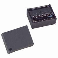
IC COUNTER ELAPSED TIME 5V 7-SIP

DS1603+

Manufacturer Part Number
DS1603+
Description
IC COUNTER ELAPSED TIME 5V 7-SIP
Manufacturer
Maxim Integrated Products
Type
Elapsed Time Counterr
Datasheet

Specifications of DS1603+

Time Format
Binary
Date Format
Binary
Interface
3-Wire Serial
Voltage - Supply
4.5 V ~ 5.5 V
Operating Temperature
0°C ~ 70°C
Mounting Type
Through Hole
Package / Case
14-DIP Module
Lead Free Status / RoHS Status
Lead free / RoHS Compliant
Memory Size
-
Note: Some revisions of this device may incorporate deviations from published specifications known as errata. Multiple revisions of any device
may be simultaneously available through various sales channels. For information about device errata, click here: www.maxim-ic.com/errata.
FEATURES
§ Two 32-bit counters keep track of real-time
§ Counters keep track of seconds for over 125
§ Battery powered counter counts seconds from
§ V
§ Clear function resets selected counter to 0
§ Read/write serial port affords low pin count
§ Powered internally by a lithium energy cell
§ One-byte protocol defines read/write, counter
§ Self-contained crystal provides an accuracy of
§ Operating temperature range of 0°C to +70°C
§ Low-profile SIP module
§ Underwriters Laboratory (UL) recognized
DESCRIPTION
The DS1603 is a real-time clock/elapsed time counter designed to count seconds when V
applied and continually count seconds under battery backup power with an additional counter regardless
of the condition of V
by using a software algorithm. The V
that V
equipment in which the DS1603 is used. Alternatively, this counter can also be used under software
control to record real-time events. Communication to and from the DS1603 takes place via a 3-wire serial
port. A 1-byte protocol selects read/ write functions, counter clear functions and oscillator trim. The
device contains a 32.768kHz crystal that will keep track of time to within 2 min/mo. An internal lithium
energy source contains enough energy to power the continuous seconds counter for over 10 years.
OPERATION
The main elements of the DS1603 are shown in Figure 1. As shown, communications to and from the
elapsed time counter occur over a 3-wire serial port. The port is activated by driving
www.maxim-ic.com
www.maxim-ic.com
and elapsed time
years
the time battery is attached until V
than 2.5V
V
absence of V
that provides over 10 years of operation
address and software clear function
±2 min per month
CC
CC
CC
powered counter counts seconds while
is above V
power is applied. This function is particularly useful in determining the operational time of
CC
TP
under battery backup power
CC
and retains the count in the
. The continuous counter can be used to derive time of day, week, month, and year
BAT
CC
powered counter will automatically record the amount of time
is less
1 of 8
Elapsed Time Counter Module
PIN ASSIGNMENT
PIN DESCRIPTION
CLK
DQ
GND
V
OSC
NC
RST
CC
GND
CLK
OSC
RST
V
DQ
NC
CC
4
1
2
3
5
6
7
- Reset
- Clock
- Data Input/Output
- Ground
- +5V
- 1Hz Oscillator Output
- No Connect
RST
to a high state.
DS1603
CC
power is
093002

Related parts for DS1603+

DS1603+ Summary of contents

Page 1

FEATURES § Two 32-bit counters keep track of real-time and elapsed time § Counters keep track of seconds for over 125 years § Battery powered counter counts seconds from the time battery is attached until V than 2.5V ...

Page 2

With at high level 8 bits are loaded into the protocol shift register providing read/write, register RST select, register clear, and oscillator trim information. Each bit is serially input on the rising edge of the clock input. After the first ...

Page 3

DATA INPUT Following the 8-bit protocol that inputs write mode, 32 bits of data are written to the selected counter on the rising edge of the next 32 CLK cycles. After 32 bits have been entered any additional CLK cycles ...

Page 4

Figure 1. ELAPSED TIME COUNTER BLOCK DIAGRAM Figure 2. PROTOCOL BIT MAP 7 6 ACC AVC OSC2 OSC1 OSC0 CCC CVC RD DS1603 ...

Page 5

Table 1. VALID PROTOCOLS ACTION ACC AVC Read Continuous 1 0 Counter Write Continuous 1 0 Counter Read V CC Active 0 1 Counter Write V CC Active 0 1 Counter Clear Continuous 0 0 Counter Clear V CC Active ...

Page 6

Figure 3. DATA TRANSFER TIMING DIAGRAM: READ/WRITE DATA TRANSFER Note and t apply to both read and write data transfer DS1603 ...

Page 7

ABSOLUTE MAXIMUM RATINGS Voltage Range on Any Pin Relative to Ground Operating Temperature Range Storage Temperature Range Soldering Temperature Range This is a stress rating only and functional operation of the device at these or any other conditions beyond t ...

Page 8

AC ELECTRICAL CHARACTERISTICS PARAMETER Data to CLK Setup CLK to Data Hold CLK to Data Delay CLK Low Time CLK High Time CLK Frequency CLK Rise and Fall to CLK Setup RST CLK to RST Hold Inactive Time RST Low ...

Page 9

DS1603 7-PIN MODULE PKG 7-PIN DIM MIN MAX A IN. 0.830 0.850 MM 21.08 21.59 B IN. 0.650 0.670 MM 16.51 17.02 C IN. 0.310 0.330 MM 7.87 8.38 D IN. 0.015 0.030 MM 0.38 0.76 E IN. 0.110 0.140 ...

Related keywords