DS1386P-32-120+ Maxim Integrated Products, DS1386P-32-120+ Datasheet
DS1386P-32-120+
Specifications of DS1386P-32-120+


Related parts for DS1386P-32-120+


DS1386P-32-120+ Summary of contents
Page 1
... DS1386-32-120+ 0°C to +70°C DS1386P-8-120 0°C to +70°C DS1386P-8-120+ 0°C to +70°C DS1386P-32-120 0°C to +70°C DS1386P-32-120+ 0°C to +70°C + Denotes a lead-free/RoHS-compliant device. * DS9034PCX PowerCap required (must be ordered separately). RAMified Watchdog Timekeeper FEATURES 8kB or 32kB of User NV RAM (RTC), ...
Page 2
PIN DESCRIPTION PIN EMOD PowerCap 32k 32k — 31 ...
Page 3
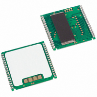
... PowerCap (DS9034PCX) that contains the crystal and battery. This design allows the PowerCap to be mounted on top of the DS1386P after the completion of the surface mount process. Mounting the PowerCap after the surface mount process prevents damage to the crystal and battery due to high temperatures required for solder reflow ...
Page 4
... The DS1386 is guaranteed to keep time accuracy to within ±1 minute per month at +25°C. CLOCK ACCURACY (POWERCAP MODULE) The DS1386P and DS9034PCX are each individually tested for accuracy. Once mounted together, the module is guaranteed to keep time accuracy to within ±1.53 minutes per month (35ppm) at +25°C. ...
Page 5
Figure 1. Block Diagram ...
Page 6
TIME-OF-DAY REGISTERS Registers 0 through A contain time, date, and alarm data in BCD. Fifteen bits within these 11 registers are not used and will always read 0 regardless of how they are written. Bits 6 and 7 in the ...
Page 7
WATCHDOG ALARM REGISTERS Registers C and D contain the time for the watchdog alarm. The two registers contain a time count from 00.01 to 99.99 seconds in BCD. The value written into the Watchdog Alarm Registers can be written or ...
Page 8
Figure 2. DS1386 RAMified Watchdog Timekeeper Registers Table 1. Time-of-Day Alarm Mask Bits REGISTER (3) MINUTES (5) HOURS Note: Any other bit combinations of mask bit settings produce illogical operation. (7) DAYS ...
Page 9
COMMAND REGISTER Address location 0Bh is the Command Register where mask bits, control bits and flag bits reside. The operation of each bit is as follows: Bit 7: TE (Transfer Enable). This bit when set to a logic 0 will ...
Page 10
ABSOLUTE MAXIMUM RATINGS Voltage Range on Any Pin Relative to Ground……………………………………………..-0.3V to +7.0V Operating Temperature Range………………………………………………………………...0°C to +70°C Storage Temperature Range………………………………………………………………...-40°C to +70°C Soldering Temperature…………………………..See IPC/JEDEC J-STD-020 Specification (See Note 14) This is a stress rating only and functional operation ...
Page 11
AC ELECTRICAL CHARACTERISTICS = 5.0V ±10 0°C to 70°C PARAMETER Read Cycle Time Address Access Time CE Access Time OE Access Time Output Active Output High-Z from Deselect Output Hold from ...
Page 12
READ CYCLE (Note 1) WRITE CYCLE 1 (Notes WRITE CYCLE 2 (Notes ...
Page 13
TIMING DIAGRAM—INTERRUPT OUTPUTS PULSE MODE (See Notes 11 and 12) POWER-DOWN/POWER-UP TIMING ...
Page 14
AC ELECTRICAL CHARACTERISTICS POWER-UP/POWER-DOWN TIMING (T = 0°C to +70°C) A PARAMETER CE High to Power Fail Recovery at Power-Up V Slew Rate Power-Down CC V Slew Rate Power-Down CC V Slew Rate Power-Up CC Expected Data Retention WARNING: Under ...
Page 15
NOTES high for a read cycle specified as the logical AND of the CE and WE going low to ...
Page 16
... A10 DQ7 DQ6 DQ0 14 19 DQ1 DQ5 15 18 DQ2 DQ4 17 16 GND DQ3 32k x 8 Encapsulated Module 1 2 N.C. 3 N.C. DS1386P 4 PFO GND V X2 BAT 16 17 32k x 8 PowerCap Module Board (Uses DS9034PCX PowerCap) INTA 34 33 SQW 32 A14 31 A13 30 A12 29 A11 ...
Page 17
PACKAGE INFORMATION (The package drawing(s) in this data sheet may not reflect the most current specifications. For the latest package outline information www.maxim-ic.com/DallasPackInfo ...
Page 18
PACKAGE INFORMATION (continued) (The package drawing(s) in this data sheet may not reflect the most current specifications. For the latest package outline information www.maxim-ic.com/DallasPackInfo ...
Page 19
PACKAGE INFORMATION (continued) (The package drawing(s) in this data sheet may not reflect the most current specifications. For the latest package outline information www.maxim-ic.com/DallasPackInfo ...
Page 20
PACKAGE INFORMATION (continued) (The package drawing(s) in this data sheet may not reflect the most current specifications. For the latest package outline information www.maxim-ic.com/DallasPackInfo ...
Page 21
... No circuit patent licenses are implied. Maxim/Dallas Semiconductor reserves the right to change the circuitry and specifications without notice at any time The Maxim logo is a registered trademark of Maxim Integrated Products, Inc. The Dallas logo is a registered trademark of Dallas Semiconductor Corporation © 2007 Maxim Integrated Products ...