TC500ACPE Microchip Technology, TC500ACPE Datasheet - Page 15
TC500ACPE
Manufacturer Part Number
TC500ACPE
Description
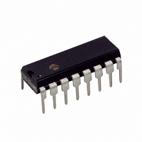
IC ANALOG FRONT END 17BIT 16DIP
Manufacturer
Microchip Technology
Specifications of TC500ACPE
Number Of Bits
17
Number Of Channels
1
Power (watts)
10mW
Voltage - Supply, Analog
5V
Voltage - Supply, Digital
4.5 V ~ 7.5 V
Package / Case
16-DIP (0.300", 7.62mm)
Resolution (bits)
17bit
Sampling Rate
10SPS
Input Channel Type
Differential
Data Interface
3-Wire, Serial
Supply Voltage Range - Analog
± 4.5V To ± 7.5V
Supply Current
1mA
Lead Free Status / RoHS Status
Lead free / RoHS Compliant
Other names
158-1022
158-1022
158-1022
Available stocks
Company
Part Number
Manufacturer
Quantity
Price

Company:
Part Number:
TC500ACPE
Manufacturer:
JRC
Quantity:
6 225
Part Number:
TC500ACPE
Manufacturer:
MIC
Quantity:
20 000


7.0
7.1
The procedure outlined below allows the user to arrive
at values for the following TC5XX design variables:
1.
2.
3.
4.
7.2
Integration time must be picked as a multiple of the
period of the line frequency. For example, T
33 ms, 66 ms and 132 ms maximize 60 Hz line
rejection.
7.3
The duration of the DINT phase is a function of the
amount of voltage stored on the integrator during T
and the value of V
immediately following INT and terminated when an
integrator output zero-crossing is detected. In general,
the maximum number of counts chosen for DINT is twice
that of INT (with V
7.4
The desired full-scale input voltage and amplifier output
current capability determine the value of R
buffer and integrator amplifiers each have a full-scale
current of 20 μA.
The value of R
following equation:
EQUATION 7-1:
7.5
C
polypropylene). The slower the conversion rate, the
larger the value C
capacitors for C
Larger values for C
limit rollover errors.
© 2008 Microchip Technology Inc.
Where:
For loop stability, R
REF
V
Integration Phase Timing.
Integrator Timing Components (R
Auto-zero and Reference Capacitors.
Voltage Reference.
IN(MAX)
and C
R
TYPICAL APPLICATIONS
Component Value Selection
Select Integration Time
DINT and IZ Phase Timing
Calculate Integrating Resistor
(R
INT
Select Reference (C
zero (C
AZ
INT
INT
R
must be low leakage capacitors (such as
=
=
)
INT
REF
REF
REF
is, therefore, directly calculated in the
AZ
INT
Maximum input voltage (full count
voltage)
Integrating Resistor (in MΩ)
(
AZ
in M
. The DINT phase must be initiated
and C
) Capacitors
should be ≥ 50 kΩ
REF
chosen at V
and C
Ω
)
AZ
must be. Recommended
=
REF
are shown in
V
---------------------- -
IN MAX
IN(MAX)
may also be used to
20
(
REF
INT
)
) and Auto-
, C
/2).
INT
INT
Table
INT
).
times of
. The
7-1.
INT
TABLE 7-1:
7.6
The integrating capacitor must be selected to maximize
integrator output voltage swing. The integrator output
voltage swing is defined as the absolute value of V
(or V
Using the 20 μA buffer maximum output current, the
value of the integrating capacitor is calculated using the
following equation.
EQUATION 7-2:
It is critical that the integrating capacitor has a very low
dielectric absorption. Polypropylene capacitors are an
example of one such dialectic. Polyester and poly-
bicarbonate capacitors may also be used in less critical
applications.
capacitors for C
TABLE 7-2:
7.7
The reference de-integration voltage is calculated
using the following equation:
EQUATION 7-3:
* Manufactured by Evox Rifa, Inc.
* Manufactured by Evox Rifa, Inc.
Where:
Conversions
Per Second
T
2 or less
INT
V
V
SS
2 to 7
S
S
>7
) less 0.9V (i.e., IV
Calculate Integrating Capacitor
(C
Calculate V
=
=
=
Value
TC500/A/510/514
V
0.22
0.33
0.47
INT
0.1
REF
C
Integration Period
IV
(TC500/A)
IV
Table 7-2
)
INT
INT
DD
DD
=
Typical Value of
C
RECOMMENDED CAPACITOR
FOR C
C
.
I or IV
I (TC510, TC514)
REF
(
---------------------------------------------------------- - V
REF
=
V
S
, C
(
-------------------------------------------- -
0.22
0.47
–
0.1
T
REF
AND C
INT
0.9
AZ
SS
summarizes recommended
INT
DD
(
2 T
V
I, whichever is less
(
SMR5 104K50J01L4
SMR5 224K50J02L4
SMR5 334K50J03L4
SMR5 474K50J04L4
) 20 10
) C
(
μ
(
(
S
F)
- 0.9VI or IV
–
INT
INT
0.9
AZ
×
Part Number*
)
SMR5 104K50J01L4
SMR5 224K50J02L4
SMR5 474K50J04L4
) R
Suggested
)
(
SELECTION
Suggested* Part
DS21428E-page 15
6 –
INT
)
Number
)
SS
+ 0.9VI).
DD
Related parts for TC500ACPE
Image
Part Number
Description
Manufacturer
Datasheet
Request
R

Part Number:
Description:
Precision Analog Front Ends
Manufacturer:
Microchip Technology Inc.
Datasheet:

Part Number:
Description:
(TC500 - TC514) Precision Analog Front Ends
Manufacturer:
Microchip Technology
Datasheet:
Part Number:
Description:
Manufacturer:
Microchip Technology Inc.
Datasheet:
Part Number:
Description:
Manufacturer:
Microchip Technology Inc.
Datasheet:
Part Number:
Description:
Manufacturer:
Microchip Technology Inc.
Datasheet:
Part Number:
Description:
Manufacturer:
Microchip Technology Inc.
Datasheet:
Part Number:
Description:
Manufacturer:
Microchip Technology Inc.
Datasheet:
Part Number:
Description:
Manufacturer:
Microchip Technology Inc.
Datasheet:
Part Number:
Description:
Manufacturer:
Microchip Technology Inc.
Datasheet:
Part Number:
Description:
Manufacturer:
Microchip Technology Inc.
Datasheet: