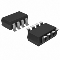
AD7999YRJZ-1500RL7 Analog Devices Inc, AD7999YRJZ-1500RL7 Datasheet - Page 2

AD7999YRJZ-1500RL7
Manufacturer Part Number
AD7999YRJZ-1500RL7
Description
IC ADC 8BIT 4CH SAR I2C SOT23-8
Manufacturer
Analog Devices Inc
Specifications of AD7999YRJZ-1500RL7
Data Interface
I²C, Serial
Design Resources
Using AD8599 as an Ultralow Distortion Driver for the AD7999 (CN0045)
Number Of Bits
8
Sampling Rate (per Second)
1M
Number Of Converters
1
Power Dissipation (max)
4.68mW
Voltage Supply Source
Single Supply
Operating Temperature
-40°C ~ 125°C
Mounting Type
Surface Mount
Package / Case
SOT-23-8
Resolution (bits)
8bit
Input Channel Type
Single Ended
Supply Voltage Range - Analogue
2.7V To 5.5V
Supply Current
850µA
No. Of Pins
8
Operating Temperature Range
-40°C To
Sampling Rate
140kSPS
Digital Ic Case Style
SOT-23
Rohs Compliant
Yes
Lead Free Status / RoHS Status
Lead free / RoHS Compliant
Other names
AD7999YRJZ-1500RL7TR
Available stocks
Company
Part Number
Manufacturer
Quantity
Price
Company:
Part Number:
AD7999YRJZ-1500RL7
Manufacturer:
ADI
Quantity:
3 000
Part Number:
AD7999YRJZ-1500RL7
Manufacturer:
ADI/亚德诺
Quantity:
20 000
AD7991/AD7995/AD7999
TABLE OF CONTENTS
Features .............................................................................................. 1
Applications....................................................................................... 1
Functional Block Diagram .............................................................. 1
General Description ......................................................................... 1
Product Highlights ........................................................................... 1
Revision History ............................................................................... 2
Specifications..................................................................................... 3
Absolute Maximum Ratings.......................................................... 11
Pin Configuration and Function Descriptions........................... 12
Typical Performance Characteristics ........................................... 13
Terminology .................................................................................... 16
Theory of Operation ...................................................................... 17
REVISION HISTORY
10/10—Rev. A to Rev. B
Changes to Max Offset Error Parameter in Table 2 ..................... 3
Changes to Max Offset Error Parameter (Y Version) in Table 3 ......5
Changes to Max Offset Error Parameter (Y Version) in Table 4 ......7
Changes to Ordering Guide...................................................................27
10/09—Rev. 0 to Rev. A
Changes to Table 3............................................................................ 5
Changes to Table 4............................................................................ 7
Updated Ordering Guide............................................................... 27
12/07—Revision 0: Initial Version
AD7991 .......................................................................................... 3
AD7995 .......................................................................................... 5
AD7999 .......................................................................................... 7
I
ESD Caution................................................................................ 11
2
C Timing Specifications............................................................ 9
Rev. B | Page 2 of 28
Internal Register Structure ............................................................ 20
Serial Interface ................................................................................ 22
Writing to the AD7991/AD7995/AD7999.................................. 23
Reading from the AD7991/AD7995/AD7999............................ 24
Mode of Operation......................................................................... 26
Outline Dimensions ....................................................................... 27
Converter Operation.................................................................. 17
Typical Connection Diagram ................................................... 18
Analog Input ............................................................................... 18
Configuration Register .............................................................. 20
Sample Delay and Bit Trial Delay............................................. 21
Conversion Result Register ....................................................... 21
Serial Bus Address...................................................................... 22
Placing the AD7991/AD7995/AD7999 into High
Speed Mode................................................................................. 25
Ordering Guide .......................................................................... 27


