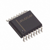
MAX110BCWE+ Maxim Integrated Products, MAX110BCWE+ Datasheet - Page 13

MAX110BCWE+
Manufacturer Part Number
MAX110BCWE+
Description
IC ADC SERIAL 2CH 14BIT 16-SOIC
Manufacturer
Maxim Integrated Products
Datasheet
1.MAX110BCPE.pdf
(24 pages)
Specifications of MAX110BCWE+
Number Of Bits
14
Sampling Rate (per Second)
50
Data Interface
MICROWIRE™, QSPI™, Serial, SPI™
Number Of Converters
1
Power Dissipation (max)
762mW
Voltage Supply Source
Single Supply
Operating Temperature
0°C ~ 70°C
Mounting Type
Surface Mount
Package / Case
16-SOIC (0.300", 7.50mm Width)
Number Of Adc Inputs
2
Architecture
Delta-Sigma
Conversion Rate
0.05 KSPs
Resolution
14 bit
Input Type
Differential
Interface Type
3-Wire (SPI, QSPI, MICROWIRE)
Voltage Reference
External
Supply Voltage (max)
5 V
Maximum Power Dissipation
762 mW
Maximum Operating Temperature
+ 70 C
Mounting Style
SMD/SMT
Minimum Operating Temperature
0 C
Lead Free Status / RoHS Status
Lead free / RoHS Compliant
Figure 6. Detailed Serial-Interface Timing
Figure 7. Common Serial-Interface Connections
+5V
SS
INTERRUPT or I/O
µP
µP
µP
INTERRUPT
MASKABLE
MASKABLE
Low-Cost, 2-Channel, ±14-Bit Serial ADCs
MISO
MOSI
P1.0
P1.1
P1.2
P1.3
P1.4
SCK
______________________________________________________________________________________
I/O
I/O
SK
SO
SI
CS
SCLK
DIN
DOUT
BUSY
c. 80C51/80C32
b. MICROWIRE
a. SPI/QSPI
t
CSH
END OF
CONVERSION
t
DA
t
DS
CS
SCLK
DOUT
DIN
BUSY
CS
SCLK
DOUT
DIN
BUSY
CS
SCLK
DIN
DOUT
BUSY
MSB
POL
t
MAX110
MAX111
MAX110
MAX111
MAX110
MAX111
t
CSS
CK
t
DH
t
t
DO
CK
OFL
MSB
The ADC serial interface operates with just SCLK, DIN,
and DOUT (allow sufficient time for the conversion to
complete between read/write operations). Achieve con-
tinuous operation by connecting BUSY to an uncommit-
ted µP I/O or interrupt, to signal the processor when the
conversion results are ready. Figures 8a and 8b show
the timing for SPI/MICROWIRE and QSPI operation.
The fully static 16-bit I/O register allows infinite time
between the two 8-bit read/write operations necessary
to obtain the full 16 bits of data with SPI and
MICROWIRE. CS must remain low during the entire
two-byte transfer (Figure 8a). QSPI allows a full 16-bit
data transfer (Figure 8b).
Figure 7c shows the general 80C32 connection to the
MAX110/MAX111 using Port 1. For a more detailed dis-
cussion, see the MAX110 evaluation kit manual.
Serial data transfer is accomplished with a 16-bit fully
static shift register. The 16-bit control word shifted into
this register during a data-transfer operation controls
the ADC’s various functions. The MSB (NO-OP)
enables/disables transfer of the control word within the
ADC. A logic 1 causes the remaining 15 bits in the con-
trol word to be transferred from the I/O register into the
control register when CS goes high, updating the
ADC’s configuration and starting a new conversion. If
Interfacing to the 80C32 Microcontroller Family
LSB
t
DO
DH
START OF
CONVERSION
I/O Shift Register
13


