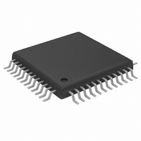
MAX1198ECM+D Maxim Integrated Products, MAX1198ECM+D Datasheet - Page 17

MAX1198ECM+D
Manufacturer Part Number
MAX1198ECM+D
Description
IC ADC 8BIT 100MSPS DUAL 48-TQFP
Manufacturer
Maxim Integrated Products
Datasheet
1.MAX1198ECMD.pdf
(22 pages)
Specifications of MAX1198ECM+D
Number Of Bits
8
Sampling Rate (per Second)
100M
Data Interface
Parallel
Number Of Converters
2
Power Dissipation (max)
314mW
Voltage Supply Source
Single Supply
Operating Temperature
-40°C ~ 85°C
Mounting Type
Surface Mount
Package / Case
48-TQFP Exposed Pad, 48-eTQFP, 48-HTQFP, 48-VQFP
Conversion Rate
100 MSPs
Resolution
8 bit
Snr
48.5 dB
Voltage Reference
2.048 V
Supply Voltage (max)
3.6 V
Supply Voltage (min)
2.7 V
Maximum Power Dissipation
1000 mW
Maximum Operating Temperature
+ 85 C
Mounting Style
SMD/SMT
Input Voltage
3.3 V
Minimum Operating Temperature
- 40 C
Lead Free Status / RoHS Status
Lead free / RoHS Compliant
Figure 8. External Buffered (MAX4250) Reference Drive Using a MAX6062 Bandgap Reference
Connecting each REFIN to analog ground disables the
internal reference of each device, allowing the internal
reference ladders to be driven directly by a set of
external reference sources. Followed by a 10Hz low-
pass filter and precision voltage-divider, the MAX6066
generates a DC level of 2.500V. The buffered outputs
of this divider are set to 2.0V, 1.5V, and 1.0V, with an
accuracy that depends on the tolerance of the divider
resistors.
These three voltages are buffered by the MAX4252,
which provides low noise and low DC offset. The indi-
vidual voltage followers are connected to 10Hz low-
pass filters, which filter both the reference voltage and
amplifier noise to a level of 3nV/√Hz. The 2.0V and 1.0V
reference voltages set the differential full-scale range
of the associated ADCs at 2V
buffers drive the ADC’s internal ladder resistances
between them.
Unbuffered External Reference Drives
with Internal Reference and Parallel Outputs
NOTE: ONE FRONT-END REFERENCE CIRCUIT DESIGN MAY BE USED WITH UP TO 1000 ADCs.
3.3V
Dual, 8-Bit, 100Msps, 3.3V, Low-Power ADC
MAX6062
1
3
______________________________________________________________________________________
2
10Hz LOWPASS
FILTER
0.1µF
16.2kΩ
1µF
P-P
0.1µF
. The 2.0V and 1.0V
Multiple ADCs
3
4
MAX4250
5
2
3.3V
1
10Hz LOWPASS
FILTER
162Ω
100µF
Note that the common power supply for all active com-
ponents removes any concern regarding power-supply
sequencing when powering up or down. With the out-
puts of the MAX4252 matching better than 0.1%, the
buffers and subsequent lowpass filters can be replicat-
ed to support as many as 32 ADCs. For applications
that require more than 32 matched ADCs, a voltage
reference and divider string common to all converters
is highly recommended.
A frequently used modulation technique in digital com-
munications applications is quadrature amplitude
modulation (QAM). Typically found in spread-spec-
trum-based systems, a QAM signal represents a carrier
frequency modulated in both amplitude and phase. At
the transmitter, modulating the baseband signal with
quadrature outputs, a local oscillator followed by sub-
sequent upconversion can generate the QAM signal.
The result is an in-phase (I) and a quadrature (Q) carri-
er component, where the Q component is 90° phase
0.1µF
Typical QAM Demodulation Application
0.1µF
2.048V
0.1µF
0.1µF
N.C.
N.C.
0.1µF
0.1µF
0.1µF
0.1µF
29
31
32
29
31
32
1
2
1
2
REFOUT
REFIN
REFP
REFN
COM
REFOUT
REFIN
REFP
REFN
COM
MAX1198
MAX1198
N = 1000
N = 1
0.1µF
2.2µF
10V
17


