4-647630-1 TE Connectivity, 4-647630-1 Datasheet - Page 2
4-647630-1
Manufacturer Part Number
4-647630-1
Description
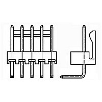
11P MTA100 HRD ASSY F/L LF
Manufacturer
TE Connectivity
Specifications of 4-647630-1
Connector Type
Header
Product Line
MTA-100
Pcb Mounting Orientation
Right Angle
Right Angle Bending Side
Front
Pcb Mount Retention
Without
Mating Connector Lock
With
Four Points Of Contact
Without
Shrouded
No
Mounting Ears
Without
Mating Connector Lock Type
Friction Lock
Post Size (mm [in])
0.64 [.025]
Panel Mount Retention
Without
Mating Post Length (mm [in])
7.37 [0.290]
Current Rating (a)
5
Voltage Rating (vac)
250
Solder Tail Contact Plating
Tin
Termination Post Length (mm [in])
3.56 [0.140]
Number Of Positions
11
Centerline (mm [in])
2.54 [0.100]
Narrow
No
Post Number(s) Omitted
None
Solder Tail Contact Material
Copper Alloy
Contact Type
Pin
Contact Shape
Square
Contact Plating, Mating Area, Material
Tin
Contact Base Material
Copper Alloy
Connector Style
Plug
Housing Color
Black
Mating Alignment
Without
Ul Flammability Rating
UL 94V-0
Housing Material
Thermoplastic - GF
Backwall/post Interruption(s)
Without
Rohs/elv Compliance
RoHS compliant, ELV compliant
Lead Free Solder Processes
Wave solder capable to 240°C
Rohs/elv Compliance History
Always was RoHS compliant
Applies To
Printed Circuit Board
Application Use
Wire-to-Board


3.3.
3.4.
3.5.
Examination of product.
Termination resistance.
Insulation resistance.
Dielectric withstanding voltage.
Temperature rise vs current.
Solderability.
Termination tensile strength,
parallel, unmated.
Termination tensile strength,
perpendicular, unmated.
Rev H
Ratings
!
!
!
Performance and Test Description
Product is designed to meet the electrical, mechanical and environmental performance requirements
specified in Figure 1. Unless otherwise specified, all tests shall be performed at ambient environmental
conditions per Test Specification 109-1.
Test Requirements and Procedures Summary
Test Description
Voltage: 250 volts AC
Current: See Figure 4 for applicable current carrying capability
Temperature:
-55 to 105° C
Meets requirements of product
drawing and Application Spec 114-
1019.
6 milliohms maximum initial.
∆R 10 milliohms maximum.
5000 megohms minimum initial.
750 vac at sea level.
1 minute hold with no breakdown or
flashover.
30° C maximum temperatur e rise at
specified current.
Solderable area shall have
minimum of 95% solder coverage.
Wire Size
Wire Size
AWG
AWG
28
24
22
28
24
22
MECHANICAL
Figure 1 (cont)
ELECTRICAL
Requirement
Pounds Minimum
Pounds Minimum
Slot Tensile
Slot Tensile
12
4
5
1
1
3
Visual, dimensional and functional
per applicable quality inspection
plan.
TE 109-6-1.
Subject mated contacts assembled
in housing to 50 mv maximum open
circuit at 100 ma maximum.
See Figures 3 and 5.
TE Spec 109-28-4.
Test between adjacent contacts of
unmated samples.
TE Spec 109-29-1.
Test between adjacent contacts of
unmated samples.
TE Spec 109-45-2.
Measure temperature rise vs
current.
See Figures 4 and 5.
TE Spec 109-11-2.
Subject contacts to solderability.
TE Spec 109-16.
Determine slot tensile at maximum
rate of 1 inch per minute. Pull
parallel to terminated wire.
See Figure 6.
TE Spec 109-16.
Determine slot tensile at maximum
rate of 1 inch per minute. Pull
perpendicular to terminated wire.
See Figure 6.
Procedure
108-1050
2 of 9
Related parts for 4-647630-1
Image
Part Number
Description
Manufacturer
Datasheet
Request
R

Part Number:
Description:
SIP IC SKT 64 SSR SN/SN ROHS
Manufacturer:
Tyco Electronics
Datasheet:
Part Number:
Description:
SIP IC SKT 64 SSR SN/AU FLH
Manufacturer:
Tyco Electronics
Datasheet:
Part Number:
Description:
SIP IC SKT 64 SSR SN/AU 0.75
Manufacturer:
Tyco Electronics
Datasheet:
Part Number:
Description:
V23533B1100G605=MESSERL. 64POL
Manufacturer:
Tyco Electronics
Datasheet:

Part Number:
Description:
Manufacturer:
TE Connectivity
Datasheet:

Part Number:
Description:
RELAY PWR SPDT 10A 24VDC PCB
Manufacturer:
TE Connectivity
Datasheet:
Part Number:
Description:
RELAY DPDT 15A 24VDC
Manufacturer:
TE Connectivity
Datasheet:
Part Number:
Description:
Electromechanical Relay SPDT 8A 12VDC 627Ohm Through Hole
Manufacturer:
TE Connectivity
Datasheet:

Part Number:
Description:
V42254P2263C960=PC612 FEDERLEI
Manufacturer:
TE Connectivity
Datasheet:
Part Number:
Description:
Manufacturer:
TE Connectivity
Datasheet:

Part Number:
Description:
Manufacturer:
TE Connectivity
Datasheet:

Part Number:
Description:
Manufacturer:
TE Connectivity
Datasheet:
Part Number:
Description:
Res Thick Film 2512 3.3K Ohm 5% 1W ±200ppm/°C Molded SMD T/R
Manufacturer:
TE Connectivity
Datasheet:

Part Number:
Description:
Conn IDC Connector F 14 POS 2.54mm IDT RA Cable Mount Loose Piece
Manufacturer:
TE Connectivity
Datasheet:

Part Number:
Description:
Manufacturer:
TE Connectivity
Datasheet: