5-641219-1 TE Connectivity, 5-641219-1 Datasheet
5-641219-1
Specifications of 5-641219-1


Related parts for 5-641219-1


5-641219-1 Summary of contents
Page 1
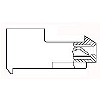
... This specification covers performance, tests and quality requirements for the TE Connectivity (TE) MTA 156 connector/header system. This system is mass terminated using insulation displacement technology on .156 inch centerlines and mates with .045 inch square or round posts providing interconnection between wires and posts mounted on printed circuit boards. Terminations are designed for 26 through 18 AWG wire having ...
Page 2
... Voltage: 600 volts AC ! Current: See Figure 4 for applicable current carrying capability ! Temperature: -55 to 105° C 3.4. Performance and Test Description Product is designed to meet the electrical, mechanical and environmental performance requirements specified in Figure 1. Unless otherwise specified, all tests shall be performed at ambient environmental conditions per Test Specification 109-1 ...
Page 3
... Calculate force per contact. TE Spec 109-42, Condition A. Measure force necessary to unmate samples from header at maximum rate of .5 inch per minute. Calculate force per contact. TE Spec 109-22. Subject mated samples to 25 cycles between -55 and 105° ...
Page 4
... See Note. Figure 1 (end) 108-1051 Procedure TE Spec 109-23-3, Condition B. Subject mated samples to 10 cycles between 25 and 65° 95% RH. TE Spec 109-43. Subject mated samples to temperature life at 105° C for gold plated contacts and 85° C for tin plated contacts for 1000 hours. TE Spec 109-85-3. ...
Page 5
... See paragraph 4.1.A. NOTE (b) Numbers indicate sequence in which tests are performed. (c) Subject half the samples to parallel tensile test and the remaining half to the perpendicular tensile test. (d) Discontinuities shall not be measured. Energize at 18 Test Specification 109-151. (e) Precondition samples with 5 cycles durability. Rev J Test Group ( ...
Page 6
... Samples shall be prepared in accordance with applicable Instruction Sheets and shall be selected at random from current production. Unless otherwise required for the test procedure, test groups and 4 shall consist of mated pairs of MTA 156 connectors and headers. Test group 1 shall consist position standard tin plated samples position high force tin plated samples; and 5, 6 position gold plated samples ...
Page 7
... Termination resistance equals millivolts divided by test current less resistance of wire length. NOTE (b) After wave soldering, printed circuit board and posts shall be cleaned to remove all flux and contaminates. Termination Resistance & Temperature Rise Measurement Points Rev J Figure 3 108-1051 ...
Page 8
... Percent Connector Loading (Tin plated 10 position in-line connector) Single Contact 50 See Note (a) 100 (a) Every other (odd) position energized NOTE (b) To determine acceptable current carrying capacity for the percentage connector loading and wire gage indicated, use the Multiplication Factor (F) from the above chart and multiply it times the Base Rated Current for a single circuit at maximum ambient operating temperature as shown in Figure 4A ...
Page 9
... Rev J Figure 5 Termination Tensile Strength 108-1051 ...
Page 10
... Rev J Figure 6 Vibration & Mechanical Shock Mounting Fixture (Use For Reference Only) 108-1051 ...