5-6610156-8 TE Connectivity, 5-6610156-8 Datasheet - Page 4
5-6610156-8
Manufacturer Part Number
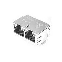
5-6610156-8
Description
1X2 MAG45(TM) 7H2,66,G/Y LED,C
Manufacturer
TE Connectivity
Specifications of 5-6610156-8
Product Type
Connector
Number Of Cores
6
Magnetics
Integrated Magnetics
Jack Type
RJ45
Signal Routing Type
Auto MDI/MDIX
Profile
Standard
Pcb Mounting Orientation
Side Entry (Right Angle)
Jack Configuration
1 x 2
Turns Ratio
1:1
Shielded
Yes
Emi Finger - Bottom
With
Termination Method
Solder
Port Configuration
Multiple
Emi Fingers -top And Sides
Without
Latch Orientation
Inverted - Latch Up
Pcb Tail Length (mm [in])
3.68 [0.145]
Contact Termination Type
Through Hole
Preloaded
Yes
Connector Style
Jack
Status Indicator
LED
Decoupling Capacitor
2KV
Rear Pcb Ground Tab
Without
Signal Lead Quantity
8
Rohs/elv Compliance
RoHS compliant, ELV compliant
Lead Free Solder Processes
Wave solder capable to 240°C, Wave solder capable to 260°C, Wave solder capable to 265°C
Rohs/elv Compliance History
Always was RoHS compliant
Left Led Color (position #1)
Green
Right Led Color (position #2)
Yellow
Operating Temperature (°c [°f])
0 – 70 [32 – 158]
Applies To
Printed Circuit Board
Environmental Conditions
Office / Premises
Application
10/100BASE-T Ethernet


Humidity, non-operational
Salt spray.
3.7.
Rev D
NOTE
Examination of product
Dry circuit resistance
Open circuit inductance
Random vibration, operational
Random vibration, non-operational
Durability, 500 cycles
Durability, 2000 cycles
Mating force
Unmating force
Normal force
Modular plug retention to modular jack
Thermal shock
Humidity-temperature cycling
Mixed flowing gas
Extended temperature
Humidity, non-operational
Salt spray
Product Qualification and Requalification Test Sequence
NOTE
Test Description
Shall meet visual requirements, show no physical damage, and meet requirements of additional
tests as specified in the Product Qualification and Requalification Test Sequence shown in
Figure 2.
Test or Examination
(a)
(b)
(c)
(d)
See paragraph 4.1.A.
Numbers indicate sequence in which tests are performed.
Measure inductance initially and at 50, 100, 150, 200, 250, 300, 350,
400, 450, 500, 550, 600, 650, 700, 750, 800, 1000, 1200, 1400, 1600,
1800 and 2000 cycles.
10 days mated; 5 days unmated; 5 days mated.
See Note.
Figure 1 (end)
Requirement
Figure 2
2, 7, 9
1, 5
3, 6
1
4
8
Test Sequence (b)
2 (d)
1, 3
Test Group (a)
2
MIL-STD-810,
Method 507.3.
Subject mated and mounted
specimens to 10 cycles (10 days)
between 30 and 60° C at 95 ± 5%
RH.
EIA-364-26,
Test Condition B.
Subject specimens to 5% spray at
35° C for 48 hours.
3
2
1
3
4
Procedure
1, 5, 8, 10
2 (c)
4
6
7
4
3
9
108-2100
4 of 6
Related parts for 5-6610156-8
Image
Part Number
Description
Manufacturer
Datasheet
Request
R

Part Number:
Description:
CONN HOUSING 66POS .100 POL DUAL
Manufacturer:
Tyco Electronics
Datasheet:

Part Number:
Description:
TRIMMER-1/2" SQ MT WW
Manufacturer:
Bourns Inc.
Datasheet:

Part Number:
Description:
1X5 MAG45(TM) 7H2,66,CAP,G/Y R
Manufacturer:
TE Connectivity
Datasheet:

Part Number:
Description:
Manufacturer:
TE Connectivity
Datasheet:

Part Number:
Description:
1X8 MAG45 7K1, 66, G/Y RLED, C
Manufacturer:
TE Connectivity
Datasheet:

Part Number:
Description:
187 FASTON REC.IS
Manufacturer:
TE Connectivity
Datasheet:

Part Number:
Description:
Conn Shrouded Header HDR 7 POS 2.54mm Solder ST Thru-Hole Tube
Manufacturer:
TE Connectivity
Datasheet:

Part Number:
Description:
Conn Shrouded Header HDR 40 POS 1.27mm Solder RA Thru-Hole Tube
Manufacturer:
TE Connectivity
Datasheet:

Part Number:
Description:
Manufacturer:
TE Connectivity
Datasheet:

Part Number:
Description:
Manufacturer:
TE Connectivity
Datasheet:

Part Number:
Description:
.050CL,CHAMP,VERT PLUG,50 POSN
Manufacturer:
TE Connectivity
Datasheet:

Part Number:
Description:
Conn Shrouded Header HDR 16 POS 2.54mm Solder ST Thru-Hole
Manufacturer:
TE Connectivity
Datasheet:

Part Number:
Description:
0.8FH,R09H.5,140,08/SN,TU
Manufacturer:
TE Connectivity
Datasheet:

Part Number:
Description:
STRAIN RELIEF, BLACK, RG59
Manufacturer:
TE Connectivity
Datasheet:

Part Number:
Description:
SOCKET, VERTICAL, 0.8MM, 13MM, 140WAY
Manufacturer:
TE Connectivity
Datasheet: