5145432-5 TE Connectivity, 5145432-5 Datasheet

CONN SEC II 31 POS W/ LATCH

5145432-5

Manufacturer Part Number
5145432-5
Description
CONN SEC II 31 POS W/ LATCH
Manufacturer
TE Connectivity
Datasheets

Specifications of 5145432-5

Product Type
Connector
Product Series
Standard Edge II
Type Of Connector
Standard
Number Of Dual Positions
31
Post Type
Solder Post
Pcb Mounting Orientation
Vertical
Mounting Ears
Without
Pcb Mount Retention
With
Pcb Retention Location
1, 3, 29, 30, 33, 34, 60, 61
High Current
No
Termination Post Length (mm [in])
3.18 [0.125]
Solder Tail Contact Plating
Tin
Centerline (mm [in])
2.54 [0.100]
Retention Latch
With
Positions Unloaded
6
Keyed Position
7, 8
Contact Plating, Mating Area, Material
Gold (30)
Contact Base Material
Phosphor Bronze
Underplate Material
Nickel
Housing Material
Polyester GF
Housing Color
Black
Rohs/elv Compliance
RoHS compliant, ELV compliant
Lead Free Solder Processes
Wave solder capable to 240°C, Wave solder capable to 260°C, Wave solder capable to 265°C
Rohs/elv Compliance History
Always was RoHS compliant
1.
1.1.
1.2.
2.
2.1.
2.2.
3.
3.1.
3.2.
3.3.
©2011 Tyco Electronics Corporation,
a TE Connectivity Ltd. Company
All Rights Reserved
TE logo is a trademark.
SCOPE
Content
This specification covers perform ance, tests and quality requirem ents for the TE Connectivity (TE)
Standard Edge connector. This connector is a m ulti-contact, edge board type assem bly having
contacts of various lengths for plug-on, wrap or solder applications.
Qualification
W hen tests are perform ed on subject product line, procedures specified in 109 Series Test
Specifications shall be used. All inspections shall be perform ed using the applicable inspection plan
and product drawing.
APPLICABLE DOCUM ENTS
The following docum ents form a part of this specification to the extent specified herein. Unless
otherwise specified, the latest edition of the docum ent applies. In the event of conflict between the
requirem ents of this specification and the product drawing, the product drawing shall take precedence.
In the event of conflict between the requirem ents of this specification the and referenced docum ents,
this specification shall take precedence.
TE Docum ents
!
!
!
Military Standard
MIL-STD-275: Printed W iring for Electronic Equipm ent
REQUIREM ENTS
Design and Construction
Product shall be of the design, construction and physical dim ensions specified on the applicable product
drawing.
Materials
!
!
Ratings
!
!
!
109-1: General Requirem ents for Test Specifications
109 Series: Test Specifications as indicated in Figure 1
501-227: Qualification Test Report
Contact: Phosphor bronze, gold plating
Housing: Polyester
Voltage: 400 volts (rm s) at sea level
Current: 3 am peres m axim um with not m ore than 6 adjacent or opposing circuits carrying this
current
Tem perature: -55 to 85°C
| Indicates change
*Trademark
Product
Specification
Connector, Standard Edge
For latest revision, visit our website at www.te.com/documents.
For Regional Customer Service, visit our website at www.te.com
Other products, logos, and company names might be trademarks of their respective owners.
108-9039
11Mar 11 Rev K
1 of 7
LOC B

Related parts for 5145432-5

5145432-5 Summary of contents

Page 1

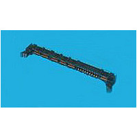
... Connector, Standard Edge 1. SCOPE 1.1. Content This specification covers perform ance, tests and quality requirem ents for the TE Connectivity (TE) Standard Edge connector. This connector ulti-contact, edge board type assem bly having contacts of various lengths for plug-on, wrap or solder applications. 1.2. Qualification W hen tests are perform ed on subject product line, procedures specified in 109 Series Test Specifications shall be used ...

Page 2

Perform ance and Test Description Product is designed to m eet the electrical, m echanical and environm ental perform ance requirem ents specified in Figure 1. All tests are perform bient tem perature unless otherwise specified. ...

Page 3

Test Description Contact retention. Durability. Therm al shock. Hum idity, steady state. Mixed flowing gas. Tem perature life. Shall meet visual requirements, show no physical damage and shall meet requirements of NOTE additional tests as specified in Test Sequence in ...

Page 4

Connector Qualification and Requalification Tests and Sequences Test or Exam ination Exam ination of product Term ination resistance, dry circuit Dielectric withstanding voltage Insulation resistance Vibration Physical shock Mating force Unm ating force Contact retention Durability Therm al shock ...

Page 5

QUALITY ASSURANCE PROVISIONS 4.1. Qualification Testing A. Sam ple Selection Connector housings and contacts shall be prepared in accordance with applicable Instruction Sheets and shall be selected at random from current production. All test groups shall consist of 10 ...

Page 6

Term ination Resistance Measurem ent Points Rev K Figure 3 Figure 4 Vibration & Physical Shock 108-9039 ...

Page 7

Connector Contact Spacing (1) Dimensions are in inches. NOTE (2) Unless otherwise specified, tolerance is ±.005. (3) Test card shall extend 4.00 ±.02 from receptacle after insertion. See Figure 3. (4) Number of contacts shall be same as on corresponding ...

Related keywords