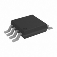
AD7887ARMZ Analog Devices Inc, AD7887ARMZ Datasheet - Page 14

AD7887ARMZ
Manufacturer Part Number
AD7887ARMZ
Description
IC ADC 12BIT 2CH SRL 8-MSOP
Manufacturer
Analog Devices Inc
Datasheet
1.AD7887WARMZ.pdf
(24 pages)
Specifications of AD7887ARMZ
Data Interface
DSP, MICROWIRE™, QSPI™, Serial, SPI™
Design Resources
Software Calibrated, 1 MHz to 8 GHz, 70 dB RF Power Measurement System Using AD8318 (CN0150)
Number Of Bits
12
Sampling Rate (per Second)
125k
Number Of Converters
1
Power Dissipation (max)
3.5mW
Voltage Supply Source
Single Supply
Operating Temperature
-40°C ~ 125°C
Mounting Type
Surface Mount
Package / Case
8-TSSOP, 8-MSOP (0.118", 3.00mm Width)
Resolution (bits)
12bit
Sampling Rate
125kSPS
Input Channel Type
Single Ended
Supply Voltage Range - Analog
2.7V To 5.25V
Supply Current
850µA
Number Of Elements
1
Resolution
12Bit
Architecture
SAR
Sample Rate
125KSPS
Input Polarity
Unipolar
Input Type
Voltage
Rated Input Volt
2.5V
Differential Input
No
Power Supply Requirement
Single
Single Supply Voltage (typ)
3.3/5V
Single Supply Voltage (min)
2.7V
Single Supply Voltage (max)
5.25V
Dual Supply Voltage (typ)
Not RequiredV
Dual Supply Voltage (min)
Not RequiredV
Dual Supply Voltage (max)
Not RequiredV
Power Dissipation
3.5mW
Differential Linearity Error
±2LSB
Integral Nonlinearity Error
±2LSB
Operating Temp Range
-40C to 125C
Operating Temperature Classification
Automotive
Mounting
Surface Mount
Pin Count
8
Package Type
MSOP
Input Signal Type
Single-Ended
Lead Free Status / RoHS Status
Lead free / RoHS Compliant
Lead Free Status / RoHS Status
Lead free / RoHS Compliant, Lead free / RoHS Compliant
Available stocks
Company
Part Number
Manufacturer
Quantity
Price
Company:
Part Number:
AD7887ARMZ
Manufacturer:
ADI
Quantity:
4 130
Part Number:
AD7887ARMZ
Manufacturer:
ADI/亚德诺
Quantity:
20 000
AD7887
second conversion can put the part back into Mode 1, and the
part goes into power-down mode when CS returns high.
Mode 2 (PM1 = 0, PM0 = 1)
In this mode of operation, the AD7887 remains fully powered
up regardless of the status of the CS line. It is intended for fastest
throughput rate performance because the user does not have to
worry about the 5 μs power-up time previously mentioned.
Figure 17
AD7887 in this mode.
The data presented to the AD7887 on the DIN line during the
first eight clock cycles of the data transfer are loaded to the
control register. To continue to operate in this mode, the user
must ensure that PM1 is loaded with 0 and PM0 is loaded with
1 on every data transfer.
The falling edge of CS initiates the sequence, and the input
signal is sampled on the second rising edge of the SCLK input.
Sixteen serial clock cycles are required to complete the conversion
and access the conversion result. Once a data transfer is complete
(that is, once CS returns high), another conversion can be initiated
immediately by bringing CS low again.
Mode 3 (PM1 = 1, PM0 = 0)
In this mode, the AD7887 automatically enters its full shutdown
mode at the end of every conversion. It is similar to Mode 1
except that the status of CS does not have any effect on the
power-down status of the AD7887.
Figure 18 shows the general diagram of the operation of the
AD7887 in this mode. On the first falling SCLK edge after CS
goes low, all on-chip circuitry starts to power up. It takes
approximately 5 μs for the AD7887 internal circuitry to be fully
powered up. As a result, a conversion (or sample-and-hold
acquisition) should not be initiated during this 5 μs. The input
signal is sampled on the second rising edge of SCLK following
the CS falling edge. The user should ensure that 5 μs elapses
shows the general diagram of the operation of the
Rev. D | Page 14 of 24
between the first falling edge of SCLK and the second rising
edge of SCLK after the CS falling edge, as shown in
In microcontroller applications (or with a slow serial clock), this
is readily achievable by driving the
port lines and ensuring that the serial data read (from the
microcontroller’s serial port) is not initiated for 5 μs. However,
for higher speed serial clocks, it will not be possible to have a
5 μs delay between powering up and the first rising edge of the
SCLK. Therefore, the user must write to the control register to
exit this mode and (by writing PM1 = 0 and PM0 = 1) put the
part into Mode 2. A second conversion needs to be initiated
when the part is powered up to get a conversion result, as
shown in
conjunction with this second conversion can put the part back
into Mode 3, and the part goes into power-down mode when
the conversion sequence ends.
Mode 4 (PM1 = 1, PM0 = 1)
In this mode, the AD7887 automatically enters a standby (or
sleep) mode at the end of every conversion. In this standby
mode, all on-chip circuitry, apart from the on-chip reference, is
powered down. This mode is similar to Mode 3, but, in this
case, the power-up time is much shorter because the on-chip
reference remains powered up at all times.
Figure 20 shows the general diagram of the operation of the
AD7887 in this mode. On the first falling SCLK edge after CS
goes low, the AD7887 comes out of standby. The AD7887 wake-
up time is very short in this mode, so it is possible to wake up
the part and carry out a valid conversion in the same read/write
operation. The input signal is sampled on the second rising
edge of SCLK following the CS falling edge. At the end of
conversion (last rising edge of SCLK), the part automatically
enters its standby mode.
Figure 19
. The write operation that takes place in
CS input from one of the
Figure 18
.


