6-66504-8 TE Connectivity, 6-66504-8 Datasheet
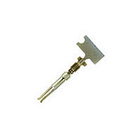
HD 20 DF SOCKET PLTD

6-66504-8

Manufacturer Part Number
6-66504-8
Description
HD 20 DF SOCKET PLTD
Manufacturer
TE Connectivity
Datasheets

Specifications of 6-66504-8

Rohs Compliant
YES
Product Type
Contact
Product Series
HDP-20 (Crimp Snap)
Termination Method To Wire/cable
Crimp
Wire Insulation Diameter (mm [in])
1.27 – 1.52 [0.050 – 0.060]
Insulation Support
Yes
Grade
Standard
Contact Retention In Housing
Crimp Snap-In
Solder Tail Contact Plating
Gold Flash over Nickel
Wire Range (mm² [awg])
0.2 - 0.6 [24-20]
Used With
CPC Connectors
Contact Type
Socket
Contact Base Material
Phosphor Bronze
Contact Plating, Mating Area, Material
Gold (50)
Contact Size
20
Rohs/elv Compliance
RoHS compliant, ELV compliant
Lead Free Solder Processes
Not relevant for lead free process
Rohs/elv Compliance History
Always was RoHS compliant
Packaging Method
Strip
Packaging Quantity
10,000/Reel
1.
1.1.
1.2.
1.3.
2.
2.1.
2.2.
2.3.
3.
3.1.
©2011 Tyco Electronics Corporation,
a TE Connectivity Ltd. Company
All Rights Reserved
TE logo is a trademark.
SCOPE
Content
This specification covers the perform ance, test and quality requirem ents for the AMPLIMITE* HDP-20
subm iniature D connectors with rem ovable F crim p contacts. The assem bly consists of a two piece
plastic housing which has integral plastic retention tines and two m etal shells which secure the housing
com ponents.
Qualification
W hen tests are perform ed on the subject product line, the procedures specified in Figure 1 shall be
used. All inspections shall be perform ed using the applicable inspection plan and product drawing.
Qualification Test Results
Successful qualification testing on the subject product line was com pleted on 06Oct89. The
Qualification Test Report num ber for this testing is 501-99. This docum entation is on file at and
available from Engineering Practices and Standards (EPS).
APPLICABLE DOCUM ENTS
The following docum ents form a part of this specification to the extent specified herein. Unless
otherwise specified, the latest edition of the docum ent applies. In the event of conflict between the
requirem ents of this specification and the product drawing, the product drawing shall take precedence.
In the event of conflict between the requirem ents of this specification and the referenced docum ents,
this specification shall take precedence.
TE Connectivity (TE) Docum ents
!
!
Industry Standard
EIA-364: Electrical Connector/Socket Test Procedures Including Environm ental Classifications
Reference Docum ent
109-197: Test Specification (AMP Test Specifications vs EIA and IEC Test Methods)
REQUIREM ENTS
Design and Construction
Product shall be of the design, construction and physical dim ensions specified on the applicable product
drawing.
114-40030: Application Specification (AMPLIMITE* HDP-20 & Econom y Crim p Snap
Subm iniature D Com m ercial Connectors)
501-99: Qualification Test Report (AMPLIMITE* HDP-20 Subm iniature D Connector W ith F Crim p
Contacts)
| Indicates change
*Trademark
Product
Specification
AMPLIMITE* HDP-20 Subminiature D Connector With F Crimp
Contacts
For latest revision, visit our website at www.te.com/documents.
For Regional Customer Service, visit our website at www.te.com
Other products, logos, and company names might be trademarks of their respective owners.
108-40005
11Mar11 Rev F
1 of 10
LOC B

Related parts for 6-66504-8

6-66504-8 Summary of contents

Page 1

... All inspections shall be perform ed using the applicable inspection plan and product drawing. 1.3. Qualification Test Results Successful qualification testing on the subject product line was com pleted on 06Oct89. The Qualification Test Report num ber for this testing is 501-99. This docum entation is on file at and available from Engineering Practices and Standards (EPS). ...

Page 2

... See Figure 3. EIA-364-6. Measure potential drop of m ated contacts assem bled in housing. Calculate resistance. See Figure 3. EIA-364-21. Test between adjacent contacts of unm ated specim ens. EIA-364-20, Condition I. 1000 volts AC at sea level. Test between adjacent contacts of unm ated specim ens ...

Page 3

... N [3 lbf] m axim um per contact. EIA-364-5. Figure 1 (continued) 108-40005 Procedure EIA-364-70, Method 1. Stabilize at a single current level until 3 readings inute intervals are within 1°C. See Figure 4. EIA-364-28, Test Condition V, Condition F. Subject m ated specim ens to 20.71 G between 50 to 2000 Hz ...

Page 4

... Measure force necessary to insert gage depth of 5 [.220 in]. See Figure 6. EIA-364-37. Size 2 tim es using gage A. Insert gage depth of 5 [.220 in] and m easure force necessary to separate gage B. See Figure 6. EIA-364-8. Determ ine crim p tensile axim um rate of 25 in] per m inute. ...

Page 5

... See paragraph 4.1.A. NOTE (b) Numbers indicate sequence in which tests are performed. (c) Discontinuities shall not be measured. Energize at 18°C level for 100% loadings per Quality Specification 102-950. Rev F Test Group ( Test Sequence ( 3,7 2,8 8 3,7 4,8 3 Figure 2 108-40005 2,5 3,6 1 ...

Page 6

... The contacts are gold flash plated. Cable clam ps are to be used on all connectors. 3. Test Group 4 shall consist of 30 each of contacts with insulation support crim ped to 24, 26, and wire. The 18, 20 and wires are crim ped to contacts without insulation support. The contacts are gold flash plated. ...

Page 7

Low Level Contact Resistance Measurem ent Points Rev F Figure 3 108-40005 ...

Page 8

... Base rated Current for a single circuit at the maximum ambient operating temperature shown in Figure 4A. Rev Maxim um W ire Gage, Continuous Operation RMS DC Figure 4A Current Carrying Capability W ire Size .384 .450 .536 .647 .237 .278 .342 .400 .164 .193 .229 .277 .132 .155 .184 .222 .114 .134 .159 .192 Figure 4B Current Rating 108-40005 .795 1 ...

Page 9

Vibration and Mechanical Shock Mounting Fixture Rev F Figure 5 108-40005 ...

Page 10

... Gage Material: High speed steel lapped finish to 1 microinch. NOTE 2. Do not change size or finish of "A" Diameter where spherical radius blends. 3. Heat Treat to RC 62-64. 4. This gage is for contact size 20. Rev F Gage Part Num ber “A” Diam eter A 92-944011-1 .0410 +.0000/-.0001 ...

Related keywords