AD7715AN-5 Analog Devices Inc, AD7715AN-5 Datasheet - Page 26
AD7715AN-5
Manufacturer Part Number
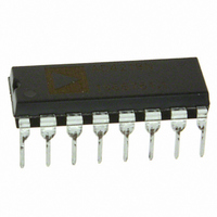
AD7715AN-5
Description
IC ADC 16BIT 5V 16-DIP
Manufacturer
Analog Devices Inc
Datasheet
1.AD7715ANZ-5.pdf
(40 pages)
Specifications of AD7715AN-5
Data Interface
DSP, MICROWIRE™, QSPI™, Serial, SPI™
Rohs Status
RoHS non-compliant
Number Of Bits
16
Sampling Rate (per Second)
500
Number Of Converters
1
Power Dissipation (max)
9.5mW
Voltage Supply Source
Analog and Digital
Operating Temperature
-40°C ~ 85°C
Mounting Type
Through Hole
Package / Case
16-DIP (0.300", 7.62mm)
Resolution (bits)
16bit
Sampling Rate
500SPS
Input Channel Type
Differential
Supply Voltage Range - Analog
4.75V To 5.25V
Supply Current
1.1mA
Digital Ic Case Style
DIP
For Use With
EVAL-AD7715-3EBZ - BOARD EVALUATION FOR AD7715
Lead Free Status / RoHS Status
Contains lead / RoHS non-compliant
Available stocks
Company
Part Number
Manufacturer
Quantity
Price
Company:

Part Number:
AD7715AN-5
Manufacturer:
AD
Quantity:
872
Company:
Part Number:
AD7715AN-5
Manufacturer:
AD
Quantity:
900
Company:
Part Number:
AD7715AN-5
Manufacturer:
AD
Quantity:
900
Part Number:
AD7715AN-5
Manufacturer:
ADI/亚德诺
Quantity:
20 000


AD7715
USING THE AD7715
CLOCKING AND OSCILLATOR CIRCUIT
The AD7715 requires a master clock input, which may be an
external CMOS compatible clock signal applied to the MCLK
IN pin with the MCLK OUT pin left unconnected. Alternatively,
a crystal or ceramic resonator of the correct frequency can be
connected between MCLK IN and MCLK OUT in which case
the clock circuit functions as an oscillator, providing the clock
source for the part. The input sampling frequency, the modula-
tor sampling frequency, the −3 dB frequency, output update
rate and calibration time are all directly related to the master
clock frequency, f
a factor of 2 will halve the above frequencies and update rate,
and double the calibration time. The current drawn from the
DV
f
affect the current drawn from the AV
Using the part with a crystal or ceramic resonator between the
MCLK IN and MCLK OUT pins generally causes more current
to be drawn from DV
driven clock signal at the MCLK IN pin. This is because the on-
chip oscillator circuit is active in the case of the crystal or ceramic
resonator. Therefore, the lowest possible current on the AD7715
is achieved with an externally applied clock at the MCLK IN pin
with MCLK OUT unconnected and unloaded.
The amount of additional current taken by the oscillator depends
on a number of factors—first, the larger the value of capacitor
placed on the MCLK IN and MCLK OUT pins, then the larger
the DV
to exceed the capacitor values recommended by the crystal and
ceramic resonator manufacturers to avoid consuming unnecessary
DV
ceramic resonator manufacturers are in the range of 30 pF to
50 pF, and if the capacitor values on MCLK IN and MCLK OUT
are kept in this range, they will not result in any excessive DV
current. Another factor that influences the DV
effective series resistance (ESR) of the crystal which appears
between the MCLK IN and MCLK OUT pins of the AD7715.
As a general rule, the lower the ESR value then the lower the
current taken by the oscillator circuit.
When operating with a clock frequency of 2.4576 MHz, there
is 50 μA difference in the DV
applied clock and a crystal resonator when operating with a
DV
typical DV
or supplied clock vs. an externally applied clock. The ESR values
for crystals and resonators at this frequency tend to be low and
as a result there tends to be little difference between different
crystal and resonator types.
CLK IN
DD
DD
DD
by a factor of 2 will halve the DV
power supply is also directly related to f
current. Typical values recommended by crystal or
of 3 V. With DV
DD
current consumption on the AD7715. Take care not
DD
current increases by 200 μA for a crystal/resonat
CLK IN
DD
. Reducing the master clock frequency by
DD
than when the part is clocked from a
= 5 V and f
DD
current between an externally
CLK IN
DD
DD
power supply.
current but does not
= 2.4576 MHz, the
CLK IN
DD
current is the
. Reducing
Rev. D | Page 26 of 40
DD
When operating with a clock frequency of 1 MHz, the ESR
value for different crystal types varies significantly. As a result,
the DV
a crystal with an ESR of 700 Ω or when using a ceramic resonator,
the increase in the typical DV
applied clock is 50 μA with DV
= 5 V. When using a crystal with an ESR of 3 kΩ, the increase in
the typical DV
with DV
The on-chip oscillator circuit also has a start-up time associated
with it before it is oscillating at its correct frequency and correct
voltage levels. The typical start-up time for the circuit is 10 ms
with a DV
depending on the loading capacitances on the MCLK pins, a
1 MΩ feedback resistor may be required across the crystal or
resonator to keep the start up times around the 15 ms duration.
The master clock of AD7715 appears on the MCLK OUT pin
of the device. The maximum recommended load on this pin is
one CMOS load. When using a crystal or ceramic resonator to
generate the clock of the AD7715, it may be desirable to then
use this clock as the clock source for the system. In this case, it
is recommended that the MCLK OUT signal is buffered with a
CMOS buffer before being applied to the rest of the circuit.
SYSTEM SYNCHRONIZATION
The FSYNC bit of the setup register allows the user to reset the
modulator and digital filter without affecting any of the setup
conditions on the part. This allows the user to start gathering
samples of the analog input from a known point in time, that is,
when the FSYNC is changed from 1 to 0.
With a 1 in the FSYNC bit of the setup register, the digital filter
and analog modulator are held in a known reset state and the
part is not processing any input samples. When a 0 is then
written to the FSYNC bit, the modulator and filter are taken
out of this reset state and on the next master clock edge the
part starts to gather samples again.
The FSYNC input can also be used as a software start convert
command allowing the AD7715 to be operated in a conven-
tional converter fashion. In this mode, writing to the FSYNC bit
starts a conversion and the falling edge of DRDY indicates when
the conversion is complete. The disadvantage of this scheme is
that the settling time of the filter has to be taken into account
for every data register update. This means that the rate at which
the data register is updated is three times slower in this mode.
DD
DD
current drain varies across crystal types. When using
DD
= 3 V and 400 μA with DV
of 5 V and 15 ms with a DV
DD
current over an externally applied clock is 100 μA
DD
DD
current over an externally-
= 3 V and 175 μA with DV
DD
= 5 V.
DD
of 3 V. At 3 V supplies,
DD
Related parts for AD7715AN-5
Image
Part Number
Description
Manufacturer
Datasheet
Request
R

Part Number:
Description:
±1.7g Dual-Axis IMEMS Accelerometer Evaluation Board
Manufacturer:
Analog Devices Inc
Datasheet:

Part Number:
Description:
Inertial Sensor Evaluation System
Manufacturer:
Analog Devices Inc
Datasheet:
Part Number:
Description:
Manufacturer:
Analog Devices Inc
Datasheet:
Part Number:
Description:
Manufacturer:
Analog Devices Inc
Datasheet:
Part Number:
Description:
Manufacturer:
Analog Devices Inc
Datasheet:
Part Number:
Description:
Manufacturer:
Analog Devices Inc
Datasheet:
Part Number:
Description:
Manufacturer:
Analog Devices Inc
Datasheet:
Part Number:
Description:
Manufacturer:
Analog Devices Inc
Datasheet:
Part Number:
Description:
Manufacturer:
Analog Devices Inc
Datasheet:
Part Number:
Description:
Manufacturer:
Analog Devices Inc
Datasheet:
Part Number:
Description:
Manufacturer:
Analog Devices Inc
Datasheet:
Part Number:
Description:
Manufacturer:
Analog Devices Inc
Datasheet:
Part Number:
Description:
Manufacturer:
Analog Devices Inc
Datasheet: