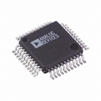
AD7864ASZ-2 Analog Devices Inc, AD7864ASZ-2 Datasheet - Page 19

AD7864ASZ-2
Manufacturer Part Number
AD7864ASZ-2
Description
IC ADC 14BIT DUAL 4CHAN 44-MQFP
Manufacturer
Analog Devices Inc
Datasheet
1.AD7864ASZ-1.pdf
(28 pages)
Specifications of AD7864ASZ-2
Data Interface
Parallel
Number Of Bits
12
Sampling Rate (per Second)
520k
Number Of Converters
1
Power Dissipation (max)
120mW
Voltage Supply Source
Analog and Digital
Operating Temperature
-40°C ~ 85°C
Mounting Type
Surface Mount
Package / Case
44-MQFP, 44-PQFP
Resolution (bits)
12bit
Sampling Rate
500kSPS
Input Channel Type
Single Ended
Supply Voltage Range - Analog
4.75V To 5.25V
Supply Current
24mA
Digital Ic Case Style
QFP
Number Of Elements
1
Resolution
12Bit
Architecture
SAR
Sample Rate
520KSPS
Input Polarity
Unipolar
Input Type
Voltage
Rated Input Volt
2.5/5V
Differential Input
No
Power Supply Requirement
Analog and Digital
Single Supply Voltage (typ)
5V
Single Supply Voltage (min)
4.75V
Single Supply Voltage (max)
5.25V
Dual Supply Voltage (typ)
Not RequiredV
Dual Supply Voltage (min)
Not RequiredV
Dual Supply Voltage (max)
Not RequiredV
Power Dissipation
120mW
Differential Linearity Error
±0.9LSB
Integral Nonlinearity Error
±1LSB
Operating Temp Range
-40C to 85C
Operating Temperature Classification
Industrial
Mounting
Surface Mount
Pin Count
44
Package Type
MQFP
Input Signal Type
Single-Ended
Lead Free Status / RoHS Status
Lead free / RoHS Compliant
Lead Free Status / RoHS Status
Lead free / RoHS Compliant, Lead free / RoHS Compliant
Available stocks
Company
Part Number
Manufacturer
Quantity
Price
Company:
Part Number:
AD7864ASZ-2
Manufacturer:
Analog Devices Inc
Quantity:
135
Company:
Part Number:
AD7864ASZ-2
Manufacturer:
Analog Devices Inc
Quantity:
10 000
Part Number:
AD7864ASZ-2
Manufacturer:
ADI/亚德诺
Quantity:
20 000
Company:
Part Number:
AD7864ASZ-2REEL
Manufacturer:
Analog Devices Inc
Quantity:
10 000
When reading the output data registers after a conversion
sequence, that is, when BUSY goes low, the register pointer is
incremented on the rising edge of the RD signal, as shown in
Figure 14
the conversion sequence, the pointer is not incremented until a
valid conversion result is in the register to be addressed. In this
case, the pointer is incremented when the conversion has ended
and the result has been transferred to the output data register.
This happens immediately before
. However, when reading the conversion results during
EOC goes low, therefore EOC
*THE POINTER IS NOT INCREMENTED BY A RISING EDGE ON RD UNTIL
RD
CS
THE CONVERSION RESULT IS IN THE OUTPUT DATA REGISTER. THE POINTER
IS RESET WHEN THE LAST CONVERSION RESULT IS READ.
COUNTER
POINTER*
RESET
2-BIT
Figure 14. Output Data Registers
OUTPUT DATA REGISTERS
Rev. D | Page 19 of 28
OE NO. 1
OE NO. 2
OE NO. 3
OE NO. 4
AD7864
NOT VALID
(V
(V
(V
may be used to enable the register contents onto the data bus,
as described in the
Conversion Sequence
Conversion Sequence
to Register 1 on the rising edge of the
conversion result in the sequence is being read. In the example
shown, this means that the pointer is set to Register 1 when the
contents of Register 3 are read.
IN1
IN3
IN4
)
)
)
DRIVERS
OUTPUT
V
DRIVE
OE
DB0 TO DB11
FRSTDATA
Reading Between Each Conversion in the
subsection within the
section. The pointer is reset to point
RD signal when the last
Selecting a
AD7864


