AD1674JNZ Analog Devices Inc, AD1674JNZ Datasheet - Page 12
AD1674JNZ
Manufacturer Part Number
AD1674JNZ
Description
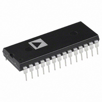
IC ADC 12BIT 100KSPS 28-DIP
Manufacturer
Analog Devices Inc
Datasheet
1.AD1674ARZ.pdf
(12 pages)
Specifications of AD1674JNZ
Data Interface
Parallel
Number Of Bits
12
Sampling Rate (per Second)
100k
Number Of Converters
1
Power Dissipation (max)
825mW
Voltage Supply Source
Dual ±
Operating Temperature
0°C ~ 70°C
Mounting Type
Through Hole
Package / Case
28-DIP (0.600", 15.24mm)
Resolution (bits)
12bit
Sampling Rate
100kSPS
Input Channel Type
Single Ended
Supply Voltage Range - Digital
4.5V To 5.5V
Supply Current
14mA
Digital Ic Case Style
DIP
Lead Free Status / RoHS Status
Lead free / RoHS Compliant
Available stocks
Company
Part Number
Manufacturer
Quantity
Price

Part Number:
AD1674JNZ
Manufacturer:
ADI/亚德诺
Quantity:
20 000


AD1674
GROUNDING
If a single AD1674 is used with separate analog and digital
ground planes, connect the analog ground plane to AGND and
the digital ground plane to DGND keeping lead lengths as short
as possible. Then connect AGND and DGND together at the
AD1674. If multiple AD1674s are used or the AD1674 shares
analog supplies with other components, connect the analog and
digital returns together once at the power supplies rather than at
each chip. This prevents large ground loops which inductively
couple noise and allow digital currents to flow through the ana-
log system.
GENERAL MICROPROCESSOR INTERFACE
CONSIDERATIONS
A typical A/D converter interface routine involves several opera-
tions. First, a write to the ADC address initiates a conversion.
The processor must then wait for the conversion cycle to com-
plete, since most ADCs take longer than one instruction cycle to
complete a conversion. Valid data can, of course, only be read
after the conversion is complete. The AD1674 provides an out-
put signal (STS) which indicates when a conversion is in
progress. This signal can be polled by the processor by reading
it through an external three-state buffer (or other input port).
The STS signal can also be used to generate an interrupt upon
completion of a conversion, if the system timing requirements
are critical (bear in mind that the maximum conversion time of
the AD1674 is only 10 microseconds) and the processor has
other tasks to perform during the ADC conversion cycle. An-
other possible time-out method is to assume that the ADC will
take 10 microseconds to convert, and insert a sufficient number
of “no-op” instructions to ensure that 10 microseconds of pro-
cessor time is consumed.
Once it is established that the conversion is finished, the data
can be read. In the case of an ADC of 8-bit resolution (or less),
a single data read operation is sufficient. In the case of convert-
ers with more data bits than are available on the bus, a choice of
data formats is required, and multiple read operations are
needed. The AD1674 includes internal logic to permit direct in-
terface to 8-bit or 16-bit data buses, selected by the 12/8 input.
In 16-bit bus applications (12/8 HIGH) the data lines (DB11
through DB0) may be connected to either the 12 most signifi-
cant or 12 least significant hits of the data bus. The remaining
four bits should be masked in software. The interface to an 8-bit
data bus (12/8 LOW) contains the 8 MSBs (DB11 through
DB4). The odd address (A
through DB0) in the upper half of the byte, followed by four
trailing zeroes, thus eliminating bit masking instructions.
AD1674 Data Format for 8-Bit Bus
0
HIGH) contains the 4 LSBs (DB3
–12–
PIN 1
0.0118 (0.30)
0.0040 (0.10)
(3.68 ±0.51)
0.145 ±0.02
(5.080)
0.200
MAX
0.175 (4.45)
0.120 (3.05)
(3.17)
0.125
28
PIN 1
1
PIN 1
MIN
0.017 ±0.003
(0.43 ±0.076)
28
28
1
28-Lead Wide-Body SO Package (R-28)
1
0.0500 (1.27)
28-Pin Ceramic DIP Package (D-28)
28-Lead Plastic DIP Package (N-28)
0.020 (0.508)
0.015 (0.381)
BSC
Dimensions shown in inches and (mm).
0.7125 (18.10)
0.6969 (17.70)
PACKAGE INFORMATION
1.440 (35.576)
0.1 (2.54)
1.450 (38.83)
0.505 (12.83)
1.42 (36.07)
1.40 (35.56)
0.105 (2.67)
0.095 (2.41)
0.0192 (0.49)
0.0138 (0.35)
(1.19 ±0.178)
0.047 ±0.007
0.065 (1.65)
0.045 (1.14)
15
14
15
14
0.2992 (7.60)
0.2914 (7.40)
0.0125 (0.32)
0.0091 (0.23)
0.1043 (2.65)
0.0926 (2.35)
15
14
0.530 (13.462)
0.160 (4.06)
0.140 (3.56)
0.550 (13.97)
SEATING
PLANE
SEATING
PLANE
0.4193 (10.65)
0.3937 (10.00)
0.050 ±0.010
(1.27 ±0.254)
(14.98 ±0.254)
0.59 ±0.01
8
0
(2.16)
0.085
°
°
0.0291 (0.74)
0.0098 (0.25)
0.606 (15.39)
0.594 (15.09)
15
0
°
0.0500 (1.27)
0.0157 (0.40)
°
0.010 ±0.002
(0.254 ±0.05)
0.6 (15.24)
0.012 (0.305)
0.008 (0.203)
x 45
REV. C
°
0.095
(2.41)
Related parts for AD1674JNZ
Image
Part Number
Description
Manufacturer
Datasheet
Request
R

Part Number:
Description:
±1.7g Dual-Axis IMEMS Accelerometer Evaluation Board
Manufacturer:
Analog Devices Inc
Datasheet:

Part Number:
Description:
Inertial Sensor Evaluation System
Manufacturer:
Analog Devices Inc
Datasheet:
Part Number:
Description:
Manufacturer:
Analog Devices Inc
Datasheet:
Part Number:
Description:
Manufacturer:
Analog Devices Inc
Datasheet:
Part Number:
Description:
Manufacturer:
Analog Devices Inc
Datasheet:
Part Number:
Description:
Manufacturer:
Analog Devices Inc
Datasheet:
Part Number:
Description:
Manufacturer:
Analog Devices Inc
Datasheet:
Part Number:
Description:
Manufacturer:
Analog Devices Inc
Datasheet:
Part Number:
Description:
Manufacturer:
Analog Devices Inc
Datasheet:
Part Number:
Description:
Manufacturer:
Analog Devices Inc
Datasheet:
Part Number:
Description:
Manufacturer:
Analog Devices Inc
Datasheet:
Part Number:
Description:
Manufacturer:
Analog Devices Inc
Datasheet:
Part Number:
Description:
Manufacturer:
Analog Devices Inc
Datasheet: