747838-6 TE Connectivity, 747838-6 Datasheet - Page 2
747838-6
Manufacturer Part Number
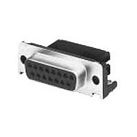
747838-6
Description
25 MSFL RCPT RA 590 (SL,FM,BL)
Manufacturer
TE Connectivity
Specifications of 747838-6
Rohs Compliant
NO
Pcb Mounting Orientation
Right Angle
Product Series
HD 20
Mating Connector Lock
With
Mating Connector Lock Type
Female Screwlocks, Fixed
Pcb Mount Retention
With
Shell Type
Front Metal Shell
Shell Size
3
Footprint (mm [in])
14.99 [.590]
Grounding Indents
Without
Grounding Straps
With
Pcb Mount Style
Through Hole
Color Code
None
Sealed
No
Profile
Standard
Post Size (mm [in])
0.66 [.026]
Mounting Hole Diameter (mm [in])
3.18 [.125]
Shell Material
Steel
Eyelet Material
Brass
Panel Mount Retention
Without
Boardlock Material
Copper Alloy
Boardlock Plating
Tin-Lead
Female Screwlock Material
Zinc
Female Screwlock Plating
Clear Chromate
Grounding Clips
Without
Termination Post Length (mm [in])
3.18 [0.125]
Solder Tail Contact Plating
Tin-Lead over Nickel
Number Of Positions
25
Pcb Mount Retention Type
Boardlock(s)
Shell Plating
Tin
Eyelet Plating
Tin
Contact Plating, Mating Area, Material
Gold (30)
Contact Shape
Round
Contact Base Material
Phosphor Bronze
Connector Style
Receptacle
Ul Flammability Rating
UL 94V-0
Housing Material
Thermoplastic - GF
Rohs/elv Compliance
Not ELV/RoHS compliant
Lead Free Solder Processes
Wave solder capable to 240°C, Wave solder capable to 260°C, Wave solder capable to 265°C
Pcb Thickness, Recommended (in [mm])
0.062 [1.57]
Application
Standard
Available stocks
Company
Part Number
Manufacturer
Quantity
Price
Company:

Part Number:
747838-6
Manufacturer:
TE Connectivity AMP Connectors
Quantity:
457


3.4.
3.5.
Rev C
Exam ination of product.
Term ination resistance, dry circuit.
Insulation resistance.
Dielectric withstanding voltage.
Tem perature rise vs current.
Solderability.
Vibration, random .
Physical shock.
Perform ance and Test Description
Product is designed to m eet the electrical, m echanical and environm ental perform ance requirem ents
specified in Figure 1. All tests are perform ed at am bient tem perature unless otherwise specified.
Test Requirem ents and Procedures Sum m ary
Test Description
15 m illiohm s m axim um initial.
Meets requirem ents of product
drawing and applicable Application
Specification.
20 m illiohm s m axim um final.
5000 m egohm s m inim um initial.
1000 m egohm s m inim um final
within 5 hours after testing.
1 kvac dielectric withstanding
voltage. 1 m inute hold. 1
m illiam pere m axim um leakage
current.
30 C m axim um tem perature rise at
specified current. 70 C m axim um
am bient.
Solderable area shall have a
m inim um of 95% solder coverage.
No discontinuities greater than 1
m icrosecond.
See Note (a).
No discontinuities greater than 1
m icrosecond.
See Note.
Figure 1 (continued)
MECHANICAL
ELECTRICAL
Requirem ent
Visual, dim ensional and functional
per applicable Quality Inspection
plan.
TE Spec 109-6-1.
Subject m ated contacts assem bled
in housings to 50 m v open circuit at
100 m a m axim um .
See Figure 3.
TE Spec 109-28-4.
Test between adjacent contacts of
unm ated assem blies.
TE Spec 109-29-1.
Test between adjacent contacts of
unm ated assem blies.
TE Spec 109-45-1.
Measure tem perature rise vs
current.
See Figure 4.
TE Spec 109-11-1.
Subject tin-lead plated contact
posts to solderability.
TE Spec 109-21-5, Level F,
20 m inute duration.
Subject m ated connectors to 20 G's
rm s with 100 m a current applied.
See Figure 3.
TE Spec 109-26-1.
Subject m ated connectors to 50 G's
half-sine shock pulses of 11
m illiseconds duration. 3 shocks in
each direction along 3 m utually
perpendicular planes, 18 total
shocks.
See Figure 3.
Procedure
108-40025
2 of 7
Related parts for 747838-6
Image
Part Number
Description
Manufacturer
Datasheet
Request
R

Part Number:
Description:
Manufacturer:
TE Connectivity
Datasheet:

Part Number:
Description:
Conn D-Subminiature RCP 25 POS 2.75mm Solder RA Thru-Hole 25 Terminal 1 Port
Manufacturer:
TE Connectivity
Datasheet:

Part Number:
Description:
Printers THERMAL PRINTER HS-SLEEVE MARKER
Manufacturer:
TE Connectivity


Part Number:
Description:
High Speed / Modular Connectors 30P HEADER ASSY
Manufacturer:
TE Connectivity
Datasheet:

Part Number:
Description:
High Speed / Modular Connectors REC 6X005P R/A LT B-PLANE HS3
Manufacturer:
TE Connectivity
Datasheet:

Part Number:
Description:
High Speed / Modular Connectors 2MM HM RCPT 50P R/A AU
Manufacturer:
TE Connectivity
Datasheet:

Part Number:
Description:
High Speed / Modular Connectors 2MM HM RCPT 50P R/A AU
Manufacturer:
TE Connectivity
Datasheet:


Part Number:
Description:
Manufacturer:
TE Connectivity
Datasheet:


Part Number:
Description:
Manufacturer:
TE Connectivity
Datasheet:

Part Number:
Description:
Manufacturer:
TE Connectivity
Datasheet:

Part Number:
Description:
Manufacturer:
TE Connectivity
Datasheet: