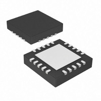
AR1020-I/ML Microchip Technology, AR1020-I/ML Datasheet - Page 21

AR1020-I/ML
Manufacturer Part Number
AR1020-I/ML
Description
IC TOUCH SCREEN CTRLR 20-QFN
Manufacturer
Microchip Technology
Type
Resistiver
Specifications of AR1020-I/ML
Resolution (bits)
10 b
Touch Panel Interface
4-Wire, 5-Wire, 8-Wire
Number Of Inputs/keys
3 Key
Data Interface
I²C, Serial, SPI™
Voltage - Supply
3.3 V ~ 5.5 V
Current - Supply
17mA
Operating Temperature
-40°C ~ 85°C
Mounting Type
Surface Mount
Package / Case
20-VQFN Exposed Pad, 20-HVQFN, 20-SQFN, 20-DHVQFN
Voltage Supply Source
Single Supply
Controller Type
Touch Screen
Ic Interface Type
I2C, SPI
Supply Voltage Range
3.3V To 5V
Operating Temperature Range
-40°C To +85°C
Digital Ic Case Style
QFN
No. Of Pins
20
Lead Free Status / RoHS Status
Lead free / RoHS Compliant
Sampling Rate (per Second)
-
Lead Free Status / RoHS Status
Lead free / RoHS Compliant, Lead free / RoHS Compliant
Available stocks
Company
Part Number
Manufacturer
Quantity
Price
Company:
Part Number:
AR1020-I/ML
Manufacturer:
MICROCHIP
Quantity:
3 400
Company:
Part Number:
AR1020-I/ML
Manufacturer:
MCP
Quantity:
5 056
Part Number:
AR1020-I/ML
Manufacturer:
MIC
Quantity:
20 000
7.12.13 PenStateReportDelay Register (offset 0x0F)
The PenStateReportDelay register sets the delay time between sending of sequential touch reports for the “Pen
Down” and “Pen Up” touch mode states. See TouchMode Register section for touch modes.
For example, if “Pen Up” state of the TouchMode register is configured to send a touch report with P=1, followed
by a touch report with P=0, then this delay occurs between the two touch reports. This provides some timing
flexibility between the two touch reports that may be desired is certain applications. Valid values are as follows.
0 ≤ PenStateReportDelay ≤ 255
Pen State Report Delay Time = PenStateReportDelay * 50μs
7.12.14 TouchReportDelay Register (offset 0x11)
The TouchReportDelay register sets a forced delay time between successive touch report packets. This allows
slowing down of the touch report rate, if desirable for a given application. For example, a given application may
not need a high rate of touch reports and may want to reduce the overhead used to service all of the touch reports
being sent. In this situation, increased the value of this register will reduce the rate at which the controller sends
touch reports. Valid values are as follows.
0 ≤ TouchReportDelay ≤ 255
Touch Report Delay Time ≈ TouchReportDelay * 500μs
7.12.15 User Configuration – Spiking
If the reported touch position contains some spiking position errors, then this can be improved by changing the
following Configuration Register values.
The trade off with the above change is that the touch report rate (points per second) will be decreased. This is
fine for many applications.
7.13 Command Format
The controller supports application specific configuration commands.
To ensure command communication is not interrupted by touch activity, it is recommended that the controller
touch is disabled, prior to other commands. This can be done as follows.
The format for sending commands is:
© 2009 Microchip Technology, Inc.
SamplingFast (offset 0x04)
AccuracyFilterFast (offset 0x06)
1) Send Disable Touch command
2) Wait 50ms
3) Send desired command/s
4) Send Enable Touch command
<Header> is defined as a value of 0x55 and is used to mark the beginning of the command packet.
<DataSize> is the number of bytes being sent in the command packet, after <DataSize>.
<Command> is a value assigned to a specific command.
<Data> represent from zero to eight bytes of command specific data.
= 8
= 8
<Header><DataSize><Command><Data>…<Data>
DS41393A-Page 17


