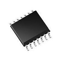
MCP4342-104E/ST Microchip Technology, MCP4342-104E/ST Datasheet - Page 37

MCP4342-104E/ST
Manufacturer Part Number
MCP4342-104E/ST
Description
IC DGTL POT QUAD 100K 14TSSOP
Manufacturer
Microchip Technology
Series
WiperLock™r
Datasheet
1.MCP4361-503EML.pdf
(80 pages)
Specifications of MCP4342-104E/ST
Package / Case
14-TSSOP
Taps
129
Resistance (ohms)
100K
Number Of Circuits
4
Temperature Coefficient
150 ppm/°C Typical
Memory Type
Non-Volatile
Interface
SPI Serial
Voltage - Supply
2.7 V ~ 5.5 V
Operating Temperature
-40°C ~ 125°C
Mounting Type
Surface Mount
Resistance In Ohms
100K
Number Of Pots
Quad
Taps Per Pot
129
Resistance
100 KOhms
Wiper Memory
Non Volatile
Buffered Wiper
Buffered
Digital Interface
SPI
Operating Supply Voltage
2.7 V to 5.5 V
Supply Current
450 uA
Maximum Operating Temperature
+ 125 C
Minimum Operating Temperature
- 40 C
Mounting Style
SMD/SMT
Supply Voltage (max)
5.5 V
Supply Voltage (min)
2.7 V
Lead Free Status / RoHS Status
Lead free / RoHS Compliant
Lead Free Status / RoHS Status
Lead free / RoHS Compliant, Lead free / RoHS Compliant
Available stocks
Company
Part Number
Manufacturer
Quantity
Price
Company:
Part Number:
MCP4342-104E/ST
Manufacturer:
Microchip
Quantity:
352
REGISTER 4-2:
© 2009 Microchip Technology Inc.
bit 8
Legend:
R = Readable bit
-n = Value at POR
bit 8
bit 7
bit 6
bit 5
bit 4
bit 3
bit 2
bit 1
bit 0
Note 1:
R-1
D8
These bits do not affect the wiper register values.
D8: Reserved. Forced to “1”
R1HW: Resistor 1 Hardware Configuration Control bit
This bit forces Resistor 1 into the “shutdown” configuration of the Hardware pin
1 = Resistor 1 is NOT forced to the hardware pin “shutdown” configuration
0 = Resistor 1 is forced to the hardware pin “shutdown” configuration
R1A: Resistor 1 Terminal A (P1A pin) Connect Control bit
This bit connects/disconnects the Resistor 1 Terminal A to the Resistor 1 Network
1 = P1A pin is connected to the Resistor 1 Network
0 = P1A pin is disconnected from the Resistor 1 Network
R1W: Resistor 1 Wiper (P1W pin) Connect Control bit
This bit connects/disconnects the Resistor 1 Wiper to the Resistor 1 Network
1 = P1W pin is connected to the Resistor 1 Network
0 = P1W pin is disconnected from the Resistor 1 Network
R1B: Resistor 1 Terminal B (P1B pin) Connect Control bit
This bit connects/disconnects the Resistor 1 Terminal B to the Resistor 1 Network
1 = P1B pin is connected to the Resistor 1 Network
0 = P1B pin is disconnected from the Resistor 1 Network
R0HW: Resistor 0 Hardware Configuration Control bit
This bit forces Resistor 0 into the “shutdown” configuration of the Hardware pin
1 = Resistor 0 is NOT forced to the hardware pin “shutdown” configuration
0 = Resistor 0 is forced to the hardware pin “shutdown” configuration
R0A: Resistor 0 Terminal A (P0A pin) Connect Control bit
This bit connects/disconnects the Resistor 0 Terminal A to the Resistor 0 Network
1 = P0A pin is connected to the Resistor 0 Network
0 = P0A pin is disconnected from the Resistor 0 Network
R0W: Resistor 0 Wiper (P0W pin) Connect Control bit
This bit connects/disconnects the Resistor 0 Wiper to the Resistor 0 Network
1 = P0W pin is connected to the Resistor 0 Network
0 = P0W pin is disconnected from the Resistor 0 Network
R0B: Resistor 0 Terminal B (P0B pin) Connect Control bit
This bit connects/disconnects the Resistor 0 Terminal B to the Resistor 0 Network
1 = P0B pin is connected to the Resistor 0 Network
0 = P0B pin is disconnected from the Resistor 0 Network
R1HW
R/W-1
TCON0 BITS
W = Writable bit
‘1’ = Bit is set
R/W-1
R1A
(1)
R/W-1
R1W
U = Unimplemented bit, read as ‘0’
‘0’ = Bit is cleared
R/W-1
R1B
R0HW
R/W-1
MCP434X/436X
x = Bit is unknown
R/W-1
R0A
R/W-1
R0W
DS22233A-page 37
R/W-1
R0B
bit 0


