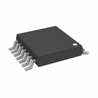
AD5241BRU1M-REEL7 Analog Devices Inc, AD5241BRU1M-REEL7 Datasheet - Page 2

AD5241BRU1M-REEL7
Manufacturer Part Number
AD5241BRU1M-REEL7
Description
IC DGTL POT 256POS 14-TSSOP
Manufacturer
Analog Devices Inc
Datasheet
1.AD5242BRUZ100-RL7.pdf
(20 pages)
Specifications of AD5241BRU1M-REEL7
Rohs Status
RoHS non-compliant
Taps
256
Resistance (ohms)
1M
Number Of Circuits
1
Temperature Coefficient
30 ppm/°C Typical
Memory Type
Volatile
Interface
I²C, 2-Wire Serial
Voltage - Supply
2.7 V ~ 5.5 V, ±2.3 V ~ 2.7 V
Operating Temperature
-40°C ~ 105°C
Mounting Type
Surface Mount
Package / Case
14-TSSOP
Resistance In Ohms
1.00M
Number Of Elements
1
# Of Taps
256
Resistance (max)
1MOhm
Power Supply Requirement
Single/Dual
Interface Type
Serial (2-Wire/I2C)
Single Supply Voltage (typ)
3/5V
Dual Supply Voltage (typ)
±2.5V
Single Supply Voltage (min)
2.7V
Single Supply Voltage (max)
5.5V
Dual Supply Voltage (min)
±2.3V
Dual Supply Voltage (max)
±2.7V
Operating Temp Range
-40C to 105C
Operating Temperature Classification
Industrial
Mounting
Surface Mount
Pin Count
14
Lead Free Status / Rohs Status
Not Compliant
AD5241/AD5242
TABLE OF CONTENTS
Features .............................................................................................. 1
Applications ....................................................................................... 1
Functional Block Diagram .............................................................. 1
General Description ......................................................................... 1
Revision History ............................................................................... 2
Specifications ..................................................................................... 3
Absolute Maximum Ratings ............................................................ 6
Pin Configurations and Function Descriptions ........................... 7
Typical Performance Characteristics ............................................. 8
REVISION HISTORY
12/09—Rev. B to Rev. C
Changes to Features Section............................................................ 1
Changes to 10 kΩ, 100 kΩ, 1 MΩ Version Section ...................... 3
Changes to Table 3 ............................................................................ 6
Deleted Digital Potentiometer Selection Guide Section ........... 14
Changed Self-Contained Shutdown Function Section to
Shutdown Function Section .......................................................... 15
Changes to Shutdown Function Section ..................................... 15
Changes to Ordering Guide .......................................................... 18
8/02—Rev. A to Rev. B
Additions to Features ....................................................................... 1
Changes to General Description .................................................... 1
Changes to Specifications ................................................................ 2
Changes to Absolute Maximum Ratings ....................................... 4
Additions to Ordering Guide .......................................................... 4
Changes to TPC 8 and TPC 9 ......................................................... 8
Changes to Readback RDAC Value Section ................................ 11
Changes to Additional Programmable Logic Output Section .. 11
Added Self-Contained Shutdown Section ................................... 12
Added Figure 8 ................................................................................ 12
Changes to Digital Potentiometer Selection Guide ................... 14
10 kΩ, 100 kΩ, 1 MΩ Version .................................................... 3
Timing Diagrams .......................................................................... 5
ESD Caution .................................................................................. 6
Rev. C | Page 2 of 20
Test Circuits ..................................................................................... 11
Theory of Operation ...................................................................... 12
Outline Dimensions ....................................................................... 16
2/02—Rev. 0 to Rev. A
Edits to Features ................................................................................. 1
Edits to Functional Block Diagrams ............................................... 1
Edits to Absolute Maximum Ratings .............................................. 4
Changes to Ordering Guide ............................................................. 4
Edits to Pin Function Descriptions ................................................. 5
Edits to Figures 1, 2, 3 ....................................................................... 6
Added Readback RDAC Value Section, Additional
Programmable Logic Output Section, and Figure 7;
Renumbered Sequentially ............................................................. 11
Changes to Digital Potentiometer Selection Guide ................... 14
Programming the Variable Resistor ......................................... 12
Programming the Potentiometer Divider ............................... 13
Digital Interface .......................................................................... 13
Readback RDAC Value .............................................................. 14
Multiple Devices on One Bus ................................................... 14
Level-Shift for Bidirectional Interface ..................................... 14
Additional Programmable Logic Output ................................ 15
Shutdown Function .................................................................... 15
Ordering Guide .......................................................................... 18


