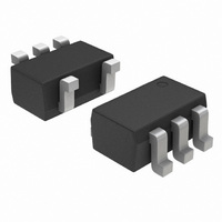
CAT5118SDI-00GT3 ON Semiconductor, CAT5118SDI-00GT3 Datasheet - Page 2

CAT5118SDI-00GT3
Manufacturer Part Number
CAT5118SDI-00GT3
Description
IC POT DPP 32TAP U/D SC70-5
Manufacturer
ON Semiconductor
Specifications of CAT5118SDI-00GT3
Taps
32
Resistance (ohms)
100K
Number Of Circuits
1
Temperature Coefficient
200 ppm/°C Typical
Memory Type
Volatile
Interface
2-Wire Serial, Up/Down
Voltage - Supply
2.7 V ~ 5.5 V
Operating Temperature
-40°C ~ 85°C
Mounting Type
Surface Mount
Package / Case
SC-70-5, SC-88A, SOT-323-5, SOT-353, 5-TSSOP
Resistance In Ohms
100K
Number Of Elements
1
# Of Taps
32
Resistance (max)
100KOhm
Power Supply Requirement
Single
Interface Type
Serial (2-Wire)
Single Supply Voltage (typ)
3.3/5V
Dual Supply Voltage (typ)
Not RequiredV
Single Supply Voltage (min)
2.7V
Single Supply Voltage (max)
5.5V
Dual Supply Voltage (min)
Not RequiredV
Dual Supply Voltage (max)
Not RequiredV
Operating Temp Range
-40C to 85C
Operating Temperature Classification
Industrial
Mounting
Surface Mount
Pin Count
5
Package Type
SC-70
Lead Free Status / RoHS Status
Lead free / RoHS Compliant
Stresses exceeding Maximum Ratings may damage the device. Maximum Ratings are stress ratings only. Functional operation above the
Recommended Operating Conditions is not implied. Extended exposure to stresses above the Recommended Operating Conditions may affect
device reliability.
1. Derate 3.1 mW/°C above T
Table 1. PIN DESCRIPTIONS
Table 2. ABSOLUTE MAXIMUM RATINGS
V
All Other Pins to GND
Input and Output Latch−Up Immunity
Maximum Continuous Current into H, L and W
Continuous Power Dissipation (T
Operating Temperature Range
Junction Temperature
Storage Temperature Range
Soldering Temperature (soldering, 10 sec)
CAT5110/
CAT5125
DD
to GND
1
2
3
4
−
5
6
100 kW
50 kW
10 kW
5−pin SC−70 (Note 1)
6−pin SC−70 (Note 1)
Pin Number
CAT5118/
CAT5123
1
2
3
4
−
−
6
A
= +70°C
CAT5119/
A
GND
CAT5124
V
U/D
Parameters
CS
= +70°C)
DD
1
2
3
4
5
−
6
Name
Figure 1. Functional Diagram
GND
V
U/D
Pin
CS
W
H
DD
L
http://onsemi.com
Power Supply
Ground
Up/Down Control Input. With CS low, a low−to−high transition increments
or decrements the wiper position.
Chip Select Input. A high−to−low CS transition determines the mode:
increment if U/D is high, or decrement if U/D is low.
Low Terminal of Resistor
Wiper Terminal of Resistor
High Terminal of Resistor
2
H
L
−0.3 to (V
W
Description
−65 to +150
−40 to +85
−0.3 to +6
Ratings
±200
+150
+300
±0.6
±1.3
±1.3
247
245
DD
+ 0.3)
Units
mW
mA
mA
°C
°C
°C
°C
V
V


