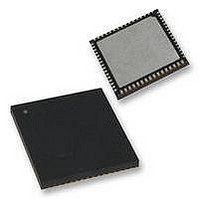
PIC18F65K90-I/MR Microchip Technology, PIC18F65K90-I/MR Datasheet - Page 337

PIC18F65K90-I/MR
Manufacturer Part Number
PIC18F65K90-I/MR
Description
32kB Flash, 2kB RAM, 1kB EE, NanoWatt XLP, LCD 64 QFN 9x9x0.9mm TUBE
Manufacturer
Microchip Technology
Series
PIC® XLP™ 18Fr
Datasheet
1.PIC18F65K90-IMR.pdf
(570 pages)
Specifications of PIC18F65K90-I/MR
Processor Series
PIC18F
Core
PIC
Data Bus Width
8 bit
Program Memory Type
Flash
Program Memory Size
32 KB
Data Ram Size
2 KB
Interface Type
I2C, SPI
Maximum Clock Frequency
64 MHz
Number Of Timers
8
Operating Supply Voltage
1.8 V to 5.5 V
Maximum Operating Temperature
+ 125 C
3rd Party Development Tools
52715-96, 52716-328, 52717-734, 52712-325, EWPIC18
Minimum Operating Temperature
- 40 C
On-chip Adc
12 bit, 16 Channel
Core Processor
PIC
Core Size
8-Bit
Speed
64MHz
Connectivity
I²C, LIN, SPI, UART/USART
Peripherals
Brown-out Detect/Reset, LCD, POR, PWM, WDT
Number Of I /o
53
Eeprom Size
1K x 8
Ram Size
2K x 8
Voltage - Supply (vcc/vdd)
1.8 V ~ 5.5 V
Data Converters
A/D 16x12b
Oscillator Type
Internal
Operating Temperature
-40°C ~ 85°C
Package / Case
64-VFQFN Exposed Pad
Lead Free Status / Rohs Status
Details
- Current page: 337 of 570
- Download datasheet (5Mb)
21.4.8
To initiate a Start condition, the user sets the Start
Enable bit, SEN (SSPxCON2<0>). If the SDAx and
SCLx pins are sampled high, the Baud Rate Generator
is reloaded with the contents of SSPxADD<6:0> and
starts its count. If SCLx and SDAx are both sampled
high when the Baud Rate Generator times out (T
the SDAx pin is driven low. The action of the SDAx
being driven low while SCLx is high is the Start condi-
tion and causes the S bit (SSPxSTAT<3>) to be set.
Following this, the Baud Rate Generator is reloaded
with the contents of SSPxADD<6:0> and resumes its
count. When the Baud Rate Generator times out
(T
automatically cleared by hardware. The Baud Rate
Generator is suspended, leaving the SDAx line held low
and the Start condition is complete.
FIGURE 21-21:
2009-2011 Microchip Technology Inc.
BRG
), the SEN bit (SSPxCON2<0>) will be
I
CONDITION TIMING
2
C™ MASTER MODE START
Write to SEN bit Occurs Here
FIRST START BIT TIMING
SDAx
SCLx
SDAx = 1,
SCLx = 1
T
BRG
BRG
),
Set S bit (SSPxSTAT<3>)
T
S
BRG
PIC18F87K90 FAMILY
At Completion of Start bit,
Hardware Clears SEN bit
21.4.8.1
If the user writes the SSPxBUF when a Start sequence
is in progress, the WCOL bit is set and the contents of
the buffer are unchanged (the write doesn’t occur).
and Sets SSPxIF bit
Note:
Note:
Write to SSPxBUF Occurs Here
T
BRG
If, at the beginning of the Start condition,
the SDAx and SCLx pins are already
sampled low, or if during the Start condi-
tion, the SCLx line is sampled low before
the SDAx line is driven low, a bus collision
occurs, the Bus Collision Interrupt Flag,
BCLxIF, is set, the Start condition is
aborted and the I
Idle state.
Because queueing of events is not
allowed, writing to the lower 5 bits of
SSPxCON2 is disabled until the Start
condition is complete.
1st bit
WCOL Status Flag
T
BRG
2nd bit
2
C module is reset into its
DS39957D-page 337
Related parts for PIC18F65K90-I/MR
Image
Part Number
Description
Manufacturer
Datasheet
Request
R

Part Number:
Description:
Manufacturer:
Microchip Technology Inc.
Datasheet:

Part Number:
Description:
Manufacturer:
Microchip Technology Inc.
Datasheet:

Part Number:
Description:
Manufacturer:
Microchip Technology Inc.
Datasheet:

Part Number:
Description:
Manufacturer:
Microchip Technology Inc.
Datasheet:

Part Number:
Description:
Manufacturer:
Microchip Technology Inc.
Datasheet:

Part Number:
Description:
Manufacturer:
Microchip Technology Inc.
Datasheet:

Part Number:
Description:
Manufacturer:
Microchip Technology Inc.
Datasheet:

Part Number:
Description:
Manufacturer:
Microchip Technology Inc.
Datasheet:


