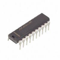
DS1802 Maxim Integrated Products, DS1802 Datasheet

DS1802
Specifications of DS1802
Available stocks
Related parts for DS1802
DS1802 Summary of contents
Page 1
... Up Control Pushbutton Inputs DC0, DC1 - Down Control Pushbutton Inputs VU Volume-Up/Volume-Down Inputs B0 Balance Pot-0, Pot-1 Inputs GND - Digital Ground MUTE - Mute AGND - Analog Ground - Zero-Crossing Detect Input ZCEN C - Cascade Output OUT DS1802 20 VCC 19 VU (UC1 (DC1 (UC0 (DC0) 15 MUTE 14 AGND 051401 ...
Page 2
... CPU controlled applications and allows the potentiometer’s exact wiper position to be read or written. Additionally, the DS1802 can be daisy-chained for multi-device environments. Figure 1 presents a block diagram of the DS1802. As shown, the inputs from the 3-wire serial interface and contact closure inputs drive a command/control unit. The command/control unit interprets these inputs for control of the two potentiometers ...
Page 3
... DS1802 BLOCK DIAGRAM Figure 1 CONTACT CLOSURE INTERFACE CONTROL The DS1802 can be configured to operate from contact closure inputs sometimes referred to as pushbutton control. There exists a total of four physical contact closure terminals on the device package. When combined with the MODE input, these contact closure inputs provide a total of eight different contact closure functions ...
Page 4
... The two input controls for balance include B0 and B1. The balance control inputs attempt to minimize their respective wiper’s attenuation. When the DS1802 first receives a balance control input, the position of the wiper closest to the high end terminal stored. ...
Page 5
... Repetitive pulsed inputs can be used to step through each resistive position of the device in a relatively fast manner (see Figure 4(b)). The requirement for repetitive pulsed inputs is that pulses must be separated by a minimum time of 1 ms. If not, the DS1802 will interpret repetitive pulses as a single pulse ...
Page 6
... Additionally, if either wiper reaches a peak position, the direction of movement will automatically reverse. For balance mode control, the B0 input will be responsible for wiper movement. A period of inactivity lasting 1 second or more will cause a switch in balance movement (i.e., balance-0 to balance-1). RST ). CLK, and D) must be grounded when DS1802 ...
Page 7
... DS1802 BALANCING EXAMPLE Figure 3 CONTACT CLOSURE TIMING (UC, DC) Figure 4 Dual Contact Closure In dual pushbutton mode, each direction is controlled by the respective cont rol inputs. No wait states are required to change wiper direction, balance, or volume in dual pushbutton mode. Additionally, in dual pushbutton mode as the wiper position reaches the end of the potentiometer, the direction of wiper movement will not change. Wiper position will remain at the potentiometers’ ...
Page 8
... If this bit has value 1, the potentiometer-0 wiper will be connected to the low end of the resistive array. The mute feature of the DS1802 will be discussed in the section entitled “Mute Operation of DS1802.” The value of bit "don’t care" and will not affect operation of the DS1802 or potentiometer-0. ...
Page 9
... I/O SHIFT REGISTER Figure 5 TIMING DIAGRAMS Figure DS1802 ...
Page 10
... CASCADE OPERATION A feature of the DS1802 is the ability to control multiple devices from a single processor. Multiple DS1802s can be linked or daisy-chained as shown in Figure bit is entered in to the I/O shift registeroftheDS1802 it will appear at the C The C output of the DS1802 can be used to drive the D input of another DS1802. When connecting ...
Page 11
... Subsequent changes when operating with continuous input pulse occur on 100 ms time intervals and are dependent on zero-crossing timeouts. MUTE CONTROL The DS1802 provides a mute control feature which can be accessed by the user through hardware or software. Hardware control of the device is achieved through the MUTE input pin. This pin is internally pulled up through potentiometers will be internally connected to the low terminal of their respective potentiometers ...
Page 12
... TYPICAL SUPPLY CURRENT VS. SERIAL CLOCK RATE Figure DS1802 ...
Page 13
... See J-STD-020A Specification SYMBOL MIN TYP -0.5 IL L,H,W GND-0.5 AGND GND-0 SYMBOL MIN TYP 400 -1 DS1802 (- +85 C) MAX UNITS NOTES 5 +0.5 V 1,2 CC +0.8 V 1 GND+0 =2.7V to 5.5V) CC MAX UNITS NOTES 2000 1000 ...
Page 14
... CAPACITANCE PARAMETER Input Capacitance Output Capacitance (- +85 C;V SYMBOL MIN TYP -20 -1 -0.5 -0.25 f 700 kHz CUTOFF 750 THD 0.002 2.2 -90 -100 Mute - SYMBOL MIN TYP OUT DS1802 =2.7V to 5.5V) CC MAX UNITS NOTES + +0.5 6 +0.25 dB 7,16 kHz ppm RMS =2.7V to 5.5V) CC MAX ...
Page 15
... UCx or DCx inputs is held active for longer than 1 second, subsequent increments or decrements will occur on 100 ms intervals until the inputs UCx, DCx are released to V pushbutton control is 30%. 6. Inter-channel matching is used to determine the relative voltage difference in dB between the same tap position on each potentiometer. The DS1802 is specified for 0.5 dB inter-channel matching SYMBOL MIN ...
Page 16
... See Figure 6. 11. Absolute tolerance is used to determine measured wiper voltage vs. expected wiper voltage as determined by wiper position. The DS1802 is bounded absolute tolerance. 12. Maximum current specifications are based on clock rate, active zero-crossing detection, and pushbutton activation. See Figure 8 for clock rate vs. current specification. ...
Page 17
... INTERNAL GROUND CONNECTIONS Figure 10 NOTE: GND and AGND must be tied to the same voltage level DS1802 ...


