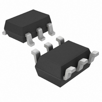
LTC2630CSC6-LM12#TRMPBF Linear Technology, LTC2630CSC6-LM12#TRMPBF Datasheet - Page 17

LTC2630CSC6-LM12#TRMPBF
Manufacturer Part Number
LTC2630CSC6-LM12#TRMPBF
Description
IC DAC 12BIT R-R SC70-6
Manufacturer
Linear Technology
Datasheet
1.LTC2630CSC6-LZ8TRMPBF.pdf
(20 pages)
Specifications of LTC2630CSC6-LM12#TRMPBF
Settling Time
4.4µs
Number Of Bits
12
Data Interface
Serial
Number Of Converters
1
Voltage Supply Source
Single Supply
Power Dissipation (max)
480µW
Operating Temperature
0°C ~ 70°C
Mounting Type
Surface Mount
Package / Case
SC-70-6, SC-88, SOT-363
Number Of Channels
1
Resolution
12b
Interface Type
Serial (3-Wire, SPI, Microwire)
Single Supply Voltage (typ)
3.3/5V
Dual Supply Voltage (typ)
Not RequiredV
Power Supply Requirement
Single
Output Type
Voltage
Integral Nonlinearity Error
±2LSB
Single Supply Voltage (min)
2.7V
Single Supply Voltage (max)
5.5V
Dual Supply Voltage (min)
Not RequiredV
Dual Supply Voltage (max)
Not RequiredV
Operating Temp Range
0C to 70C
Operating Temperature Classification
Commercial
Mounting
Surface Mount
Pin Count
6
Package Type
SC-70
Lead Free Status / RoHS Status
Lead free / RoHS Compliant
Other names
LTC2630CSC6-LM12#TRMPBFTR
Available stocks
Company
Part Number
Manufacturer
Quantity
Price
OPERATION
Optoisolated 4mA to 20mA Process Controller
Figure 5 shows how to use an LTC2630HZ to make an
optoisolated, digitally-controlled 4mA to 20mA transmitter.
The transmitter circuitry, including optoisolation, is
powered by the loop voltage which has a wide range of
5.4V to 80V. The 5V output of the LT
set the 4mA offset current and V
control the 0mA to 16mA signal current. The supply
current for the regulator, DAC, and op amp is well below
the 4mA budget at zero scale. R
current, which includes the quiescent supply current and
CS/LD
SCK
SDI
X
1
X
2
CS/LD
X
SCK
SDI
3
8 DON’T-CARE BITS
X
4
X
C3
5
1
COMMAND WORD
X
C2
6
2
Figure 3a. 24-Bit Load Sequence (Minimum Input Word)
LTC2630-12 SDI Data Word: 12-Bit Input Code + 4 Don’t-Care Bits (Shown);
LTC2630-10 SDI Data Word: 10-Bit Input Code + 6 Don’t-Care Bits;
LTC2630-8 SDI Data Word: 8-Bit Input Code + 8 Don’t-Care Bits
Figure 3b. 32-Bit Load Sequence
LTC2630-12 SDI Data Word: 12-Bit Input Code + 4 Don’t-Care Bits (Shown);
LTC2630-10 SDI Data Word: 10-Bit Input Code + 6 Don’t-Care Bits;
LTC2630-8 SDI Data Word: 8-Bit Input Code + 8 Don’t-Care Bits
X
C1
7
3
X
C0
8
4
S
OUT
C3
X
9
COMMAND WORD
senses the total loop
4 DON’T-CARE BITS
5
C2
®
10
is used to digitally
X
3010-5 is used to
6
C1
X
11
7
C0
12
X
8
D11
X
13
4 DON’T-CARE BITS
32-BIT INPUT WORD
9
D10
X
14
10
X
D9
15
11
24-BIT INPUT WORD
X
D8
16
12
D11
additional current through Q1. Note that at the maximum
loop voltage of 80V, Q1 will dissipate 1.6W when I
20mA and must have an appropriate heat sink.
R
for controlling a 4mA to 20mA output as the digital input
varies from zero scale to full scale. Alternatively, R
can be a 365k, 1% resistor in series with a 20k trim pot
and R
trim pot. The optoisolators shown will limit the speed of
the serial bus; the 6N139 is an alternative that will allow
higher data rates.
D7
17
13
OFFSET
D10
D6
18
14
GAIN
D9
D5
19
15
and R
D8
DATA WORD
D4
can be a 75.0k, 1% resistor in series with a 5k
20
16
D7
D3
21
GAIN
17
D6
D2
22
18
are the closest 0.1% values to ideal
D5
D1
23
19
DATA WORD
D4
D0
24
20
D3
X
25
21
D2
26
X
22
D1
27
X
23
D0
28
X
24
LTC2630
X
29
2630 F03a
X
30
X
31
17
OFFSET
X
32
OUT
2630fe
2630 F03b
=


