1-2154159-3 TE Connectivity, 1-2154159-3 Datasheet - Page 2
1-2154159-3
Manufacturer Part Number
1-2154159-3
Description
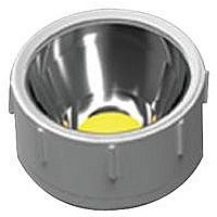
LED LIGHT MODULE, WHITE, 3420LM
Manufacturer
TE Connectivity
Series
NEVALOr
Specifications of 1-2154159-3
Led Module Type
Board + LED
Led Color
White
Cct
4000K
Luminous Flux @ Test
3420lm
Power Module Configuration
Circular
Forward Current @ Test
2.1A
Color
White, Neutral
Luminous Flux @ Current - Test
3420lm
Current - Test
2.1A
Current - Max
3A
Driver Circuitry
Yes
Voltage
30V
Wavelength
4000K
Configuration
Circular
With Connector
Yes
Lead Free Status / Rohs Status
Lead free / RoHS Compliant


3.2. Mounting the Circular Light Module (CN88)
Rev A
CAUTION
CAUTION
CAUTION
1. Once the heat sink has been properly sized and
prepared for the application of the Circular Light
Module (CN88), the base sub-assembly (base
housing, screws, protection cover, PCBA, LED, and
TIM) can be aligned over the mounting holes.
Mounting screws to be alternately tightened to a
torque of 0.28 to 0.45 N
Figure 3. The protective cover can now be removed.
2. The reflector is then installed, aligning three
keyways. Reflector posts have a slight click-fit into
the light engine holes. Firmly seat the optic in place.
See Figure 4.
3. The top ring (with compression ring
pre-assembled) is then lowered over the light
module, aligning three (3) pegs in the top ring to
three (3) guide features in the base. With a slight
downward pressure (to compress the compression
ring and a clockwise twist), you will feel and hear a
tactile and audible click. This secures the top ring
on the Circular Light Module (CN88) and completes
the assembly. See Figure 5. Refer to Application
!
!
!
When mounting the module, care must be taken
not to damage the light module and LEDs with the
screwdriver used for tightening the mounting
screws. The protection cover is protecting the LED
during this operation.
If the clear protective layer on the TIM material is
not removed, optimum thermal performance will not
be achieved.
TE recommends that when handling the reflector,
that non-marking gloves be used. The reflector
should be handled by the outer diameter to
eliminate the chance of leaving marks within the
light emitting area.
m [2.5 to 4.0 in.-lbf]. See
Thermal Interface Material
Clear Protective Layer
Figure 3
Specification 114-13290 for information on
assembly procedures on the NEVALO Interconnect
System.
Figure 4
408-10424
2 of 3
Related parts for 1-2154159-3
Image
Part Number
Description
Manufacturer
Datasheet
Request
R

Part Number:
Description:
FLA STEGEHZ
Manufacturer:
TE Connectivity
Datasheet:

Part Number:
Description:
IC SS CLOCK GENERATOR 16-TSSOP
Manufacturer:
Cypress Semiconductor Corp
Datasheet:
Part Number:
Description:
IC SS CLOCK GENERATOR 16-TSSOP
Manufacturer:
Cypress Semiconductor Corp
Datasheet:

Part Number:
Description:
AMP MCP 2.8 SOCKET HSG.,21POS.ASSY
Manufacturer:
TE Connectivity
Datasheet:

Part Number:
Description:
Manufacturer:
TE Connectivity
Datasheet:

Part Number:
Description:
JUN-POW-TIM GEH 21P
Manufacturer:
TE Connectivity
Datasheet:

Part Number:
Description:
FLACHSTE-GEH2,8 21P
Manufacturer:
TE Connectivity
Datasheet:

Part Number:
Description:
Manufacturer:
TE Connectivity
Datasheet:
Part Number:
Description:
Power to the Board JUN-POW-TIM GEH 21P
Manufacturer:
TE Connectivity
Datasheet:
Part Number:
Description:
Power to the Board JUN-POW-TIM GEH 21P
Manufacturer:
TE Connectivity
Datasheet:
Part Number:
Description:
Manufacturer:
TE Connectivity
Datasheet:

Part Number:
Description:
Manufacturer:
IDT, Integrated Device Technology Inc
Datasheet:
Part Number:
Description:
Manufacturer:
IDT, Integrated Device Technology Inc
Datasheet:


Part Number:
Description:
CONN BARRIER BLOCK 21POS 9.53MM
Manufacturer:
Tyco Electronics