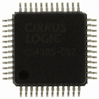
CS4385-CQZ Cirrus Logic Inc, CS4385-CQZ Datasheet - Page 22

CS4385-CQZ
Manufacturer Part Number
CS4385-CQZ
Description
IC DAC 8CH 114DB 192KHZ 48LQFP
Manufacturer
Cirrus Logic Inc
Specifications of CS4385-CQZ
Package / Case
48-LQFP
Number Of Bits
24
Data Interface
Serial
Number Of Converters
8
Voltage Supply Source
Analog and Digital
Power Dissipation (max)
520mW
Operating Temperature
-40°C ~ 85°C
Mounting Type
Surface Mount
Conversion Rate
216 KSPS
Resolution
24 bit
Interface Type
Serial
Operating Supply Voltage
5 V
Operating Temperature Range
+ 85 C
Maximum Power Dissipation
390 mW
Mounting Style
SMD/SMT
Number Of Dac Outputs
8
Lead Free Status / RoHS Status
Lead free / RoHS Compliant
For Use With
598-1154 - BOARD EVAL FOR CS4385 DAC
Settling Time
-
Lead Free Status / Rohs Status
Lead free / RoHS Compliant
Other names
598-1063
Available stocks
Company
Part Number
Manufacturer
Quantity
Price
Company:
Part Number:
CS4385-CQZ
Manufacturer:
CIRRUS
Quantity:
638
Company:
Part Number:
CS4385-CQZ
Manufacturer:
CRYSTAL
Quantity:
170
Part Number:
CS4385-CQZ
Manufacturer:
CIRRUS
Quantity:
20 000
Company:
Part Number:
CS4385-CQZR
Manufacturer:
Cirrus Logic Inc
Quantity:
10 000
Part Number:
CS4385-CQZR
Manufacturer:
CIRRUS
Quantity:
20 000
22
4.2
Mode Select
In Hardware Mode, operation is determined by the Mode Select pins. The states of these pins are continu-
ally scanned for any changes; however, the mode should only be changed while the device is in reset
(RST pin low) to ensure proper switching from one mode to another. These pins require connection to sup-
ply or ground as outlined in
Tables 4
In Software Mode, the operational mode and data format are set in the FM and DIF registers. See
Control (address 03h)” on page
(DIF1)
M2
0
0
0
0
1
1
1
1
M1
M4
0
0
1
1
0
0
0
0
1
1
1
-
6
show the decode of these pins.
(DIF0)
M1
M3
0
0
1
1
0
0
1
1
M0
0
0
1
1
0
0
1
0
1
0
1
Table 4. PCM Digital Interface Format, Hardware Mode Options
Table 6. Direct Stream Digital (DSD), Hardware Mode Options
Left-Justified, up to 24-bit data
I²S, up to 24-bit data
Right-Justified, 16-bit Data
Right-Justified, 24-bit Data
(DEM)
M0
Figure
0
1
0
1
0
1
0
1
M2
Table 5. Mode Selection, Hardware Mode Options
X
0
1
0
1
0
1
38.
8. For M0, M1, and M2, supply is VLC. For M3 and M4, supply is VLS.
64x oversampled DSD data with a 4x MCLK to DSD data rate
64x oversampled DSD data with a 6x MCLK to DSD data rate
64x oversampled DSD data with a 8x MCLK to DSD data rate
64x oversampled DSD data with a 12x MCLK to DSD data rate
128x oversampled DSD data with a 2x MCLK to DSD data rate
128x oversampled DSD data with a 3x MCLK to DSD data rate
128x oversampled DSD data with a 4x MCLK to DSD data rate
128x oversampled DSD data with a 6x MCLK to DSD data rate
Single-Speed without De-Emphasis (4 to 50 kHz sample rates)
Single-Speed with 44.1 kHz De-Emphasis; see
Double-Speed (50 to 100 kHz sample rates)
Quad-Speed (100 to 200 kHz sample rates)
Auto Speed-Mode Detect (32 kHz to 200 kHz sample rates)
Auto Speed-Mode Detect with 44.1 kHz De-Emphasis; see
DSD Processor Mode (see
DESCRIPTION
Table 6
DESCRIPTION
DESCRIPTION
for details)
FORMAT
Figure 20
0
1
2
3
Figure 20
FIGURE
CS4385
DS671F2
10
11
12
9
“PCM


